6 layers58.4 × 156.2 mm
LAUNCHXL F280049C KICAD
MiniNugen/Custom_Inverter_Hardware
PCBProjectNameREV1.PrjPCB | Source Documents | | PCBProjectNameREV1.SchDOC | | PCBProjectNameREV1.PcbDOC | | BOM | Settings | Libraries
237 parts1

 themarcolab/Stardrive-Shield2
With STARDRIVE SHIELD you can implement from 6 step to FOC motor control algorithms.
STARDRIVE SHIELD V1 0 is an open-source printed circuit board by themarcolab, from the themarcolab/Stardrive-Shield repository on GitHub. It is a 4-layer board of 97 × 105.5 mm with 193 parts on 136 nets, routed with 871 tracks and 2,102 vias.
It is built around the L7983PU50R, STDRIVE101 and BSZ099N06LS5, with the LD1117S33TR(MS), TJA1051TK/3/1 and BAT43WS among its other parts. Its parts include 58 capacitors, 55 resistors, 21 diodes, 14 connectors and 13 ICs.


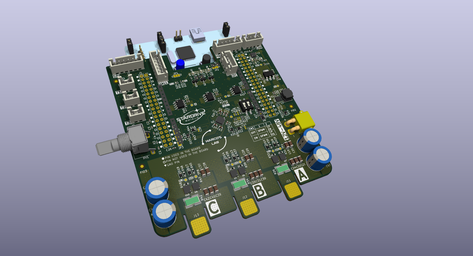
This project has been born because I have been trying to develop an ESC (hardware and firmware) on my own. While the most challenging part has been the firmware (being myself a hardware guy), the most frustrating part has been not finding a flexible hardware platform to develop upon.
So I designed one: STARDRIVE SHIELD
This is a project with the goal of creating a NUCLEO-64 compatible shield to be used as a flexible platform to develop and test ESC firmware, but also for educational purposes. To do so, I included as many features as possible. These features are not mandatory, but they can be implemented (or not) in the firmware (e.g. SPI, I2C, CAN, HALL) or configured through the hardware interface (e.g. overcurrent protection, 6 or 3 PWM). In this way, the STARDRIVE SHIELD grants flexibility to the developer and it is adapt to various needs.
The STARDRIVE SHIELD is built around the STDRIVE101 gate driver and implementing BSZ099N06LS5 MOSFETs. It presents 3 in-line shunt resistors and 3 relative INA240A2 current sense amplifiers.
With STARDRIVE SHIELD you can implement from 6 step to FOC motor control algorithms.
I designed it to be compatible with Nucleo-G474 and Nucleo-F446. Compatibility with other boards has to be verified.
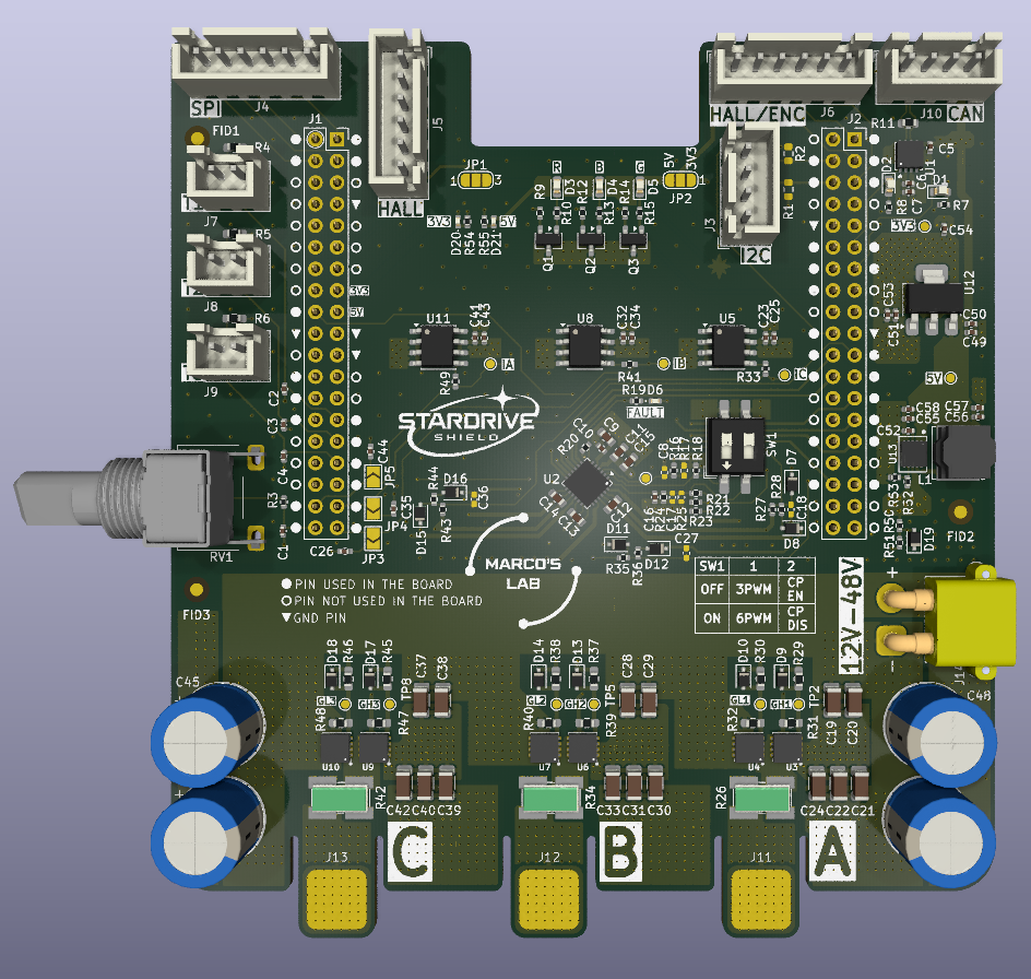
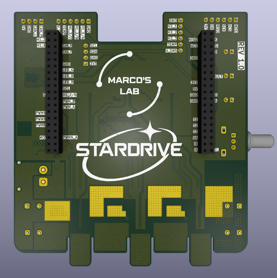
For this project I took inspiration from the VESC Project and EVALSTDRIVE101
| Qty | Value | Footprint | References |
|---|---|---|---|
| 15 | 4u7 100V | Capacitor_SMD:C_1206_3216Metric | C19, C20, C21, C22, C24, C28, C29, C30, C31, C33, C37, C38, C39, C40, C42 |
| 13 | BAT43WS | Diode_SMD:D_SOD-323F | D7, D8, D9, D10, D11, D12, D13, D14, D15, D16, D17, D18, D19 |
| 12 | TestPoint | TestPoint:TestPoint_Pad_D1.0mm | TP1, TP2, TP3, TP4, TP5, TP6, TP7, TP8, TP9, TP10, TP11, TP12 |
| 9 | 100n 10V | Capacitor_SMD:C_0402_1005Metric | C1, C7, C8, C25, C34, C43, C50, C51, C55 |
| 9 | 10k | Resistor_SMD:R_0603_1608Metric_Pad0.98x0.95mm_HandSolder | R4, R5, R6, R31, R32, R39, R40, R47, R48 |
| 8 | 2u2 10V | Capacitor_SMD:C_0402_1005Metric | C2, C3, C4, C5, C6, C23, C32, C41 |
| 6 | 10u 10V | Capacitor_SMD:C_0402_1005Metric | C49, C53, C54, C56, C57, C58 |
| 6 | 54R9 | Resistor_SMD:R_0603_1608Metric_Pad0.98x0.95mm_HandSolder | R29, R30, R37, R38, R45, R46 |
| 6 | BSZ099N06LS5 | 00_myFootprints:PG-TSDSON-8 | U3, U4, U6, U7, U9, U10 |
| 5 | 360R | Resistor_SMD:R_0402_1005Metric | R7, R8, R10, R13, R55 |
| 4 | 0R | Resistor_SMD:R_0402_1005Metric_Pad0.72x0.64mm_HandSolder | R16, R33, R41, R49 |
| 4 | 100R | Resistor_SMD:R_0402_1005Metric | R3, R9, R12, R14 |
| 4 | 10k | Resistor_SMD:R_0402_1005Metric | R20, R21, R22, R23 |
| 4 | 220u 63V | Capacitor_THT:CP_Radial_D10.0mm_P5.00mm | C45, C46, C47, C48 |
| 4 | 3k3 | Resistor_SMD:R_0402_1005Metric | R28, R36, R44, R51 |
| 4 | 56k | Resistor_SMD:R_0402_1005Metric | R27, R35, R43, R50 |
| 3 | 100n 10V | Capacitor_SMD:C_0402_1005Metric_Pad0.74x0.62mm_HandSolder | C26, C35, C44 |
| 3 | 1mR | Resistor_SMD:R_Shunt_Ohmite_LVK25 | R26, R34, R42 |
| 3 | 1u 25V | Capacitor_SMD:C_0603_1608Metric | C12, C13, C14 |
| 3 | Conn_01x02_Pin | Connector_JST:JST_XH_B2B-XH-A_1x02_P2.50mm_Vertical | J7, J8, J9 |
| 3 | Conn_01x06_Pin | Connector_JST:JST_XH_B6B-XH-A_1x06_P2.50mm_Vertical | J4, J5, J6 |
| 3 | Fiducial | Fiducial:Fiducial_1.5mm_Mask3mm | FID1, FID2, FID3 |
| 3 | INA241A3xD | Package_SO:SOIC-8_3.9x4.9mm_P1.27mm | U5, U8, U11 |
| 3 | LOGO | LOGO | G***, G***, G*** |
| 3 | NMOS | Package_TO_SOT_SMD:SOT-23-3 | Q1, Q2, Q3 |
| 3 | NP | Capacitor_SMD:C_0402_1005Metric_Pad0.74x0.62mm_HandSolder | C18, C27, C36 |
| 3 | SolderJumper_2_Open | Jumper:SolderJumper-2_P1.3mm_Open_TrianglePad1.0x1.5mm | JP3, JP4, JP5 |
| 3 | ~ | 00_myFootprints:Pad 8x8mm | J11, J12, J13 |
| 2 | Conn_01x04_Pin | Connector_JST:JST_XH_B4B-XH-A_1x04_P2.50mm_Vertical | J3, J10 |
| 2 | Conn_02x19_Odd_Even | Connector_PinSocket_2.54mm:PinSocket_2x19_P2.54mm_Vertical | J1, J2 |
| 2 | GREEN | LED_SMD:LED_0603_1608Metric | D1, D3 |
| 2 | GREEN | LED_SMD:LED_0402_1005Metric | D20, D21 |
| 2 | NP | Resistor_SMD:R_0603_1608Metric | R1, R2 |
| 2 | RED | LED_SMD:LED_0603_1608Metric | D2, D5 |
| 2 | SolderJumper_3_Open | Jumper:SolderJumper-3_P1.3mm_Open_RoundedPad1.0x1.5mm_NumberLabels | JP1, JP2 |
| 1 | 100k | Resistor_SMD:R_0402_1005Metric | R52 |
| 1 | 100n 100V | Capacitor_SMD:C_0603_1608Metric | C11 |
| 1 | 100n 25V | Capacitor_SMD:C_0402_1005Metric | C10 |
| 1 | 120R | Resistor_SMD:R_0603_1608Metric | R11 |
| 1 | 15k | Resistor_SMD:R_0402_1005Metric | R53 |
| 1 | 1k1 | Resistor_SMD:R_0402_1005Metric | R24 |
| 1 | 1u 100V | Capacitor_SMD:C_0603_1608Metric | C15 |
| 1 | 220R | Resistor_SMD:R_0402_1005Metric | R54 |
| 1 | 3n3 10V | Capacitor_SMD:C_0402_1005Metric | C16 |
| 1 | 470R | Resistor_SMD:R_0402_1005Metric | R19 |
| 1 | 470n 10V | Capacitor_SMD:C_0402_1005Metric | C52 |
| 1 | 4u7 25V | Capacitor_SMD:C_0603_1608Metric | C9 |
| 1 | 51k | Resistor_SMD:R_0402_1005Metric_Pad0.72x0.64mm_HandSolder | R18 |
| 1 | 620R | Resistor_SMD:R_0402_1005Metric | R15 |
| 1 | 68u | Inductor_SMD:L_Bourns_SRN6045TA | L1 |
| 1 | BLUE | LED_SMD:LED_0603_1608Metric | D4 |
| 1 | Conn_01x02_Socket | Connector_AMASS:AMASS_XT30PW-M_1x02_P2.50mm_Horizontal | J14 |
| 1 | L7983 | 00_myFootprints:DFN-10-1EP_3mmX3mm_P0.5mm_ExposedPad_0.62x0.98mm | U13 |
| 1 | LD1117S33TR_SOT223 | Package_TO_SOT_SMD:SOT-223-3_TabPin2 | U12 |
| 1 | LOGO | 00_myFootprints:MARCO_LAB_LOGO_15x15 | G*** |
| 1 | NP | Capacitor_SMD:C_0402_1005Metric | C17 |
| 1 | NP | Resistor_SMD:R_0402_1005Metric_Pad0.72x0.64mm_HandSolder | R17 |
| 1 | NP | Resistor_SMD:R_0402_1005Metric | R25 |
| 1 | NUCLEO-64 | 00_myFootprints:NUCLEO-64 | BRD1 |
| 1 | NetTie_2 | NetTie:NetTie-2_SMD_Pad2.0mm | NT1 |
| 1 | RED | LED_SMD:LED_0402_1005Metric | D6 |
| 1 | R_Potentiometer_MountingPin | Potentiometer_THT:Potentiometer_Alps_RK09L_Single_Horizontal | RV1 |
| 1 | STDRIVE101 | Package_DFN_QFN:QFN-24-1EP_4x4mm_P0.5mm_EP2.8x2.8mm_ThermalVias | U2 |
| 1 | SW_DIP_x02 | Button_Switch_SMD:SW_DIP_SPSTx02_Slide_6.7x6.64mm_W8.61mm_P2.54mm_LowProfile | SW1 |
| 1 | TJA1051TK-3 | Package_SON:HVSON-8-1EP_3x3mm_P0.65mm_EP1.6x2.4mm | U1 |
It measures 97 × 105.5 mm and has 4 copper layers, 1.6 mm thick.
193 parts, built around the L7983PU50R, STDRIVE101, BSZ099N06LS5 and LD1117S33TR(MS). The full list of its parts is on this page, with links to each part's symbol and footprint where PCBKit's library has them.
From the themarcolab/Stardrive-Shield repository on GitHub, at the commit this page was made from: the board is STARDRIVE_SHIELD_V1_0.kicad_pcb and its schematic Connectors.kicad_sch. PCBKit opens the board in the browser, with nothing to install.
Its repository states no licence, so its author keeps all rights: ask themarcolab before reusing the design.
MiniNugen/Custom_Inverter_Hardware
PCBProjectNameREV1.PrjPCB | Source Documents | | PCBProjectNameREV1.SchDOC | | PCBProjectNameREV1.PcbDOC | | BOM | Settings | Libraries

Manul-Electronics/sp1_reader
Standalone reader based on an ESP32 for P1 protocol

Sepios/connection_board
The KiCad files (schemes, layouts, gerbers) for the Sepios connection board.

toby-lane-amodo/ARIA_SRB_FAFF_2_POC_CBs_1_FABLE_5_1
Electronics for FAFF 2 — a linear actuator with force feedback, built as an OEM-style module for soft-material characterisation. CBs1 is the proof-of-concept control board.

EwoudVV/ducktop2
An open-source 16-inch laptop designed from scratch.


antmicro/m2-smart-iot-module
https://antmicro.com/blog/2021/08/open-hardware-smart-m2-radio-module-for-iot/