4 layers97 × 105.5 mm
STARDRIVE SHIELD V1 0
themarcolab/Stardrive-Shield
With STARDRIVE SHIELD you can implement from 6 step to FOC motor control algorithms.
193 parts2
 Manul-Electronics/sp1_reader
Standalone reader based on an ESP32 for P1 protocol
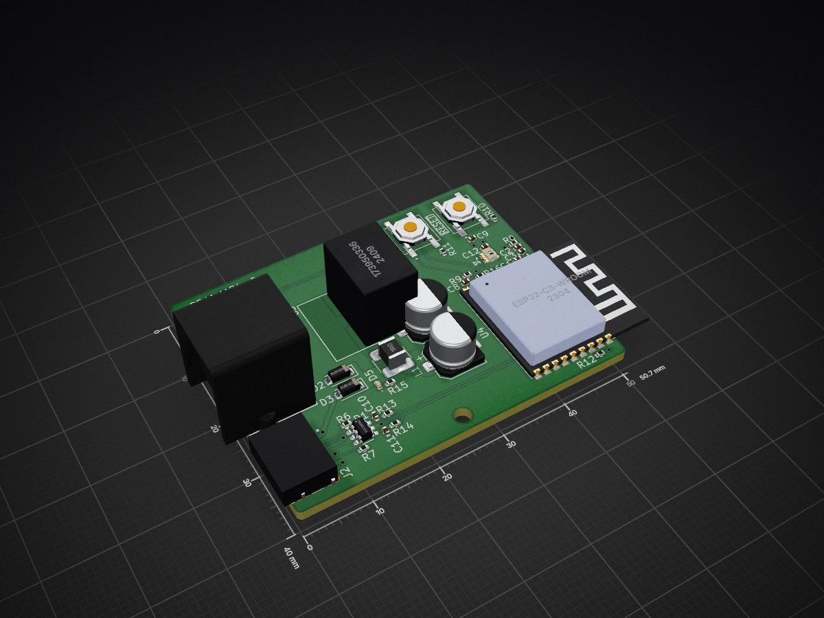
P1 wireless indicator is an open-source printed circuit board by Manul-Electronics, from the Manul-Electronics/sp1_reader repository on GitHub. It is a 4-layer board of 50.7 × 40 mm with 42 parts on 45 nets, routed with 138 tracks and 19 vias.
It is built around the ESP32-C3-WROOM-02-N4, CRCW040210K0FKEDHP and CRCW0402220RFKEDC, with the RC0402JR-070RL, 0402ZD106MAT2A and 1N5819HW-7-F-01 among its other parts. Its parts include 16 resistors, 12 capacitors, 5 diodes, 4 ICs and 2 connectors. It belongs with the ESP32 and RISC-V boards of this library.


Smart Meter serial to wireless interface (Wi-Fi).
| Qty | Value | Footprint | References |
|---|---|---|---|
| 6 | 10K | Resistor_SMD:R_0402_1005Metric | R1, R4, R8, R9, R12, R16 |
| 5 | 220R | Resistor_SMD:R_0402_1005Metric | R3, R5, R10, R11, R15 |
| 4 | 100nF | Capacitor_SMD:C_0402_1005Metric | C2, C8, C9, C12 |
| 2 | 0R | Resistor_SMD:R_0402_1005Metric | R13, R14 |
| 2 | 10uF | Capacitor_SMD:CP_Elec_6.3x5.7 | C4, C5 |
| 2 | 10uF | Capacitor_SMD:C_0402_1005Metric | C1, C3 |
| 2 | 140357145100 | manul_tech:140357145100 | U1, U2 |
| 2 | 1N5819W | Diode_SMD:D_SOD-123 | D2, D3 |
| 2 | 22uF | Capacitor_SMD:C_1210_3225Metric | C6, C7 |
| 2 | 5.1K | Resistor_SMD:R_0402_1005Metric | R6, R7 |
| 2 | KSEM31JLFS | manul_tech:KSEM31JLFS | SW1, SW2 |
| 2 | TBD | Capacitor_SMD:C_0402_1005Metric | C10, C11 |
| 1 | 173950336 | manul_tech:SIP3_11.6x8.5mm | U3 |
| 1 | 1M | Resistor_SMD:R_0402_1005Metric | R17 |
| 1 | 1uH | manul_tech:7447730 | L1 |
| 1 | 615006138421 | manul_tech:615006138421 | J1 |
| 1 | 629722000214 | manul_tech:629722000214 | J2 |
| 1 | 82400102 | Package_TO_SOT_SMD:SOT-23-6 | D1 |
| 1 | ESP32-C3-WROOM-02-N4 | manul_tech:MODULE_ESP32-C3-WROOM-02-H4 | U4 |
| 1 | PWR | LED_SMD:LED_0402_1005Metric | D5 |
| 1 | WS2812C-2020 | manul_tech:LED_WS2812C-2020 | D4 |
It measures 50.7 × 40 mm and has 4 copper layers, 1.6 mm thick.
42 parts, built around the ESP32-C3-WROOM-02-N4, CRCW040210K0FKEDHP, CRCW0402220RFKEDC and RC0402JR-070RL. The full list of its parts is on this page, with links to each part's symbol and footprint where PCBKit's library has them.
From the Manul-Electronics/sp1_reader repository on GitHub, at the commit this page was made from: the board is Hardware/p1_wireless_indicator.kicad_pcb and its schematic Hardware/cpu.kicad_sch. PCBKit opens the board in the browser, with nothing to install.
Its repository states no licence, so its author keeps all rights: ask Manul-Electronics before reusing the design.
themarcolab/Stardrive-Shield
With STARDRIVE SHIELD you can implement from 6 step to FOC motor control algorithms.

ramb0t/Shroomgon
Moon-themed Tildagon hexpansion app for the EMF badge (ESP32-S3) - 7x SK6812 LEDs, gyro-driven moon phase, auto-runs from an I2C EEPROM.


ripclap/rm520n-carrier
KiCad RM520N-GL carrier with 2.5 GbE, passive PoE, dual SIM interfaces and independent LoRa management.

TENNLab-UTK/NWRIST
Code and KiCAD PCB design for the NWRIST: Neuromorphic Wearable for Real-Time Intelligent Sensing Technology paper


OliviezGit/FC_01
Le dossier composants contient les fiches techniques PDF, bibliothèques locales, STEP, vues de contrôle et la nomenclature France du 27/09/2026.

antmicro/m2-smart-iot-module
https://antmicro.com/blog/2021/08/open-hardware-smart-m2-radio-module-for-iot/