2 layers100 × 60.5 mm
WizServoTester
Abean2k/WizServoTester
A servo controller PCB that can control up to 4 servos using onboard controls and a simple web app.
40 parts5MIT
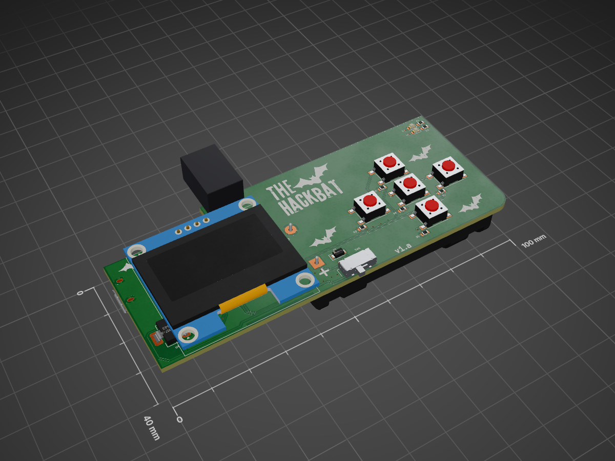
 thehackbat/hackbat_esp3212
Hackbat version based on the ESP32C6
Hackbat is an open-source printed circuit board by thehackbat, from the thehackbat/hackbat_esp32 repository on GitHub. It is a 2-layer board of 99.9 × 40 mm with 68 parts on 50 nets, routed with 478 tracks and 84 vias.
It is built around the CC1101RGP, ESP32-C6-WROOM-1-N8 and AMS1117-3.3. Its parts include 23 resistors, 12 capacitors, 6 switches, 4 ICs and 4 inductors. It belongs with the ESP32 and RISC-V boards of this library.


New version of the Hackbat tool, this time based on the ESP32 C6.
NOTE: This version is still under test, so minor changes can be applied.
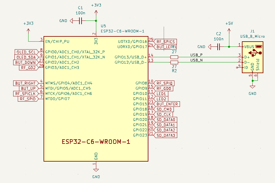
The new version of hackbat features a powerful ESP32C6 from Espressif. This microcontroller features a dual core RISC-V processor, WIFI6, BT LE and a bunch of peripherals.
The package used is the WROOM-1, but it is also compatible with the 1U model adding an external antenna.
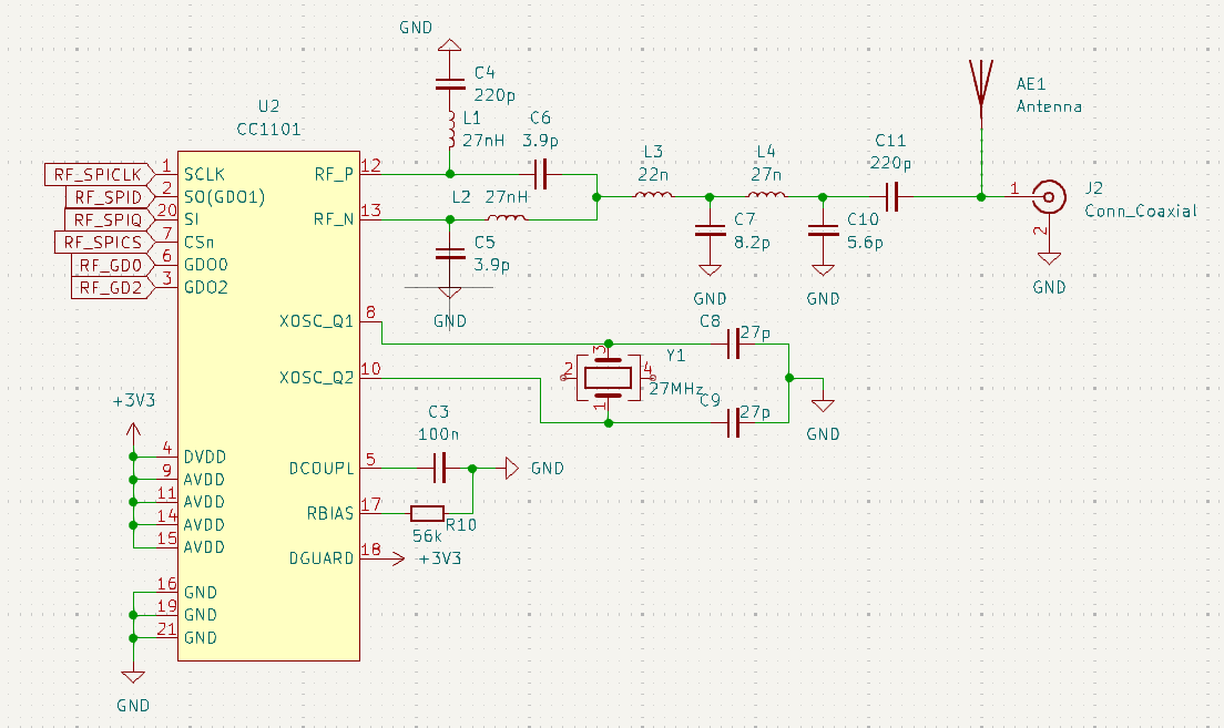
Like the original, the Hackbat ESP32 features an RF tranceiver, the CC1101 from Texas Instruments.
The CC1101 is a low-cost sub-1 GHz transceiver designed for very low-power wireless applications. The circuit is mainly intended for the ISM (Industrial, Scientific and Medical) and SRD (Short Range Device) frequency bands at 315, 433, 868, and 915 MHz, but can easily be programmed for operation at other frequencies in the 300-348 MHz, 387-464 MHz and 779-928 MHz bands
The Hackbat ESP32 board includes an antenna, but can be also populate the J2 connector in order to add an SMA antenna.
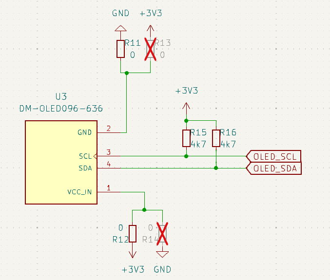
A monochrome OLED is added as an interface. The driver used in the ESP-IDF IDE is able to work with the SH1106, and ssd1306
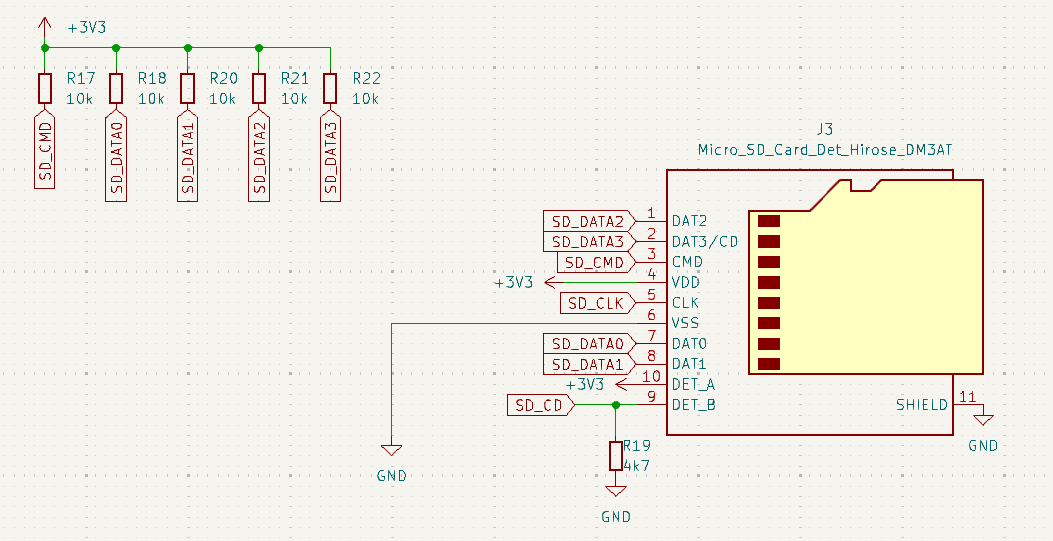
The SD Card in this version uses the SDIO interface with the microcontroller, so the speed is increased with respect the first version of the board.
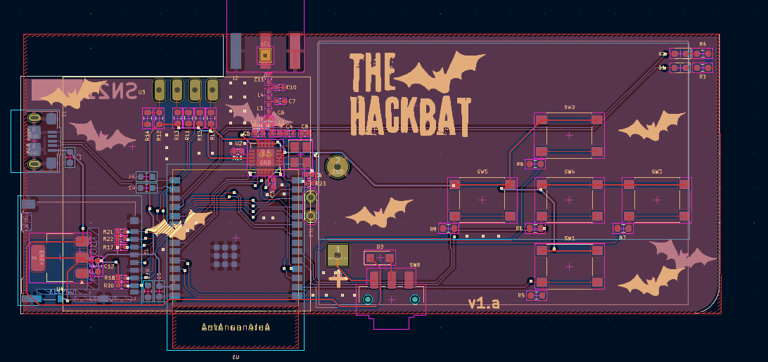
The layout of the board is 2-layer with components in both layers.
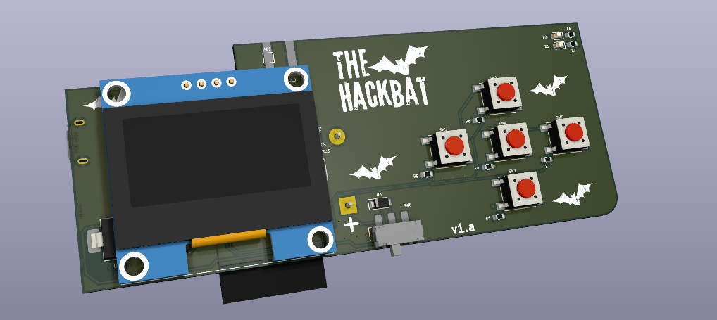
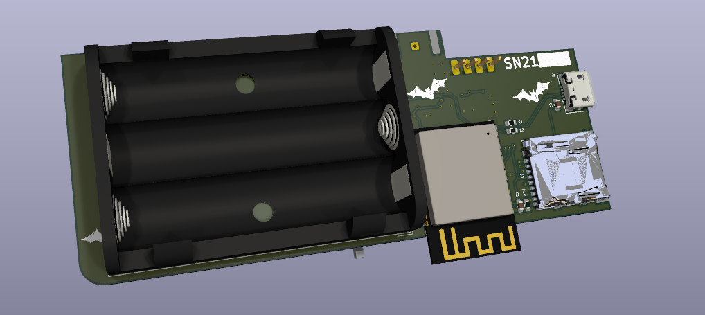
This project is open-source so you can build your own Hackbat by sending the production files to JLCPCB.
JLCPCB not only will manufacture your PCB, but they can also asembly your board. To do that, you have to use the BOM and the Centroid files provided in the production_files folder.
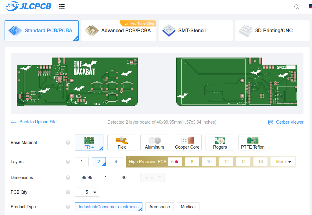
Remember to change the Surface Finish to LeadFree HASL to make your board ROHS compliant. Also, the original board uses a Black PCB color, so if you want to keep your Hackbat like the original, you can select this color to be sure that the silkscreen is seen correctly.
In a few days, you will receive your board at home.
| Qty | Value | Footprint | References |
|---|---|---|---|
| 10 | 4k7 | Resistor_SMD:R_0603_1608Metric | R3, R4, R5, R6, R7, R8, R9, R15, R16, R19 |
| 8 | LOGO | IMG:bat | G***, G***, G***, G***, G***, G***, G***, G*** |
| 6 | 10k | Resistor_SMD:R_0402_1005Metric | R17, R18, R20, R21, R22, R23 |
| 5 | SW_Push | Button_Switch_SMD:SW_Push_1P1T_NO_6x6mm_H9.5mm | SW1, SW2, SW3, SW4, SW5 |
| 4 | 0 | Resistor_SMD:R_0603_1608Metric | R11, R12, R13, R14 |
| 2 | 100n | Capacitor_SMD:C_0603_1608Metric | C1, C2 |
| 2 | 220p | Capacitor_SMD:C_0402_1005Metric | C4, C11 |
| 2 | 27 | Resistor_SMD:R_0603_1608Metric | R1, R2 |
| 2 | 27nH | Inductor_SMD:L_0402_1005Metric | L1, L2 |
| 2 | 27p | Capacitor_SMD:C_0402_1005Metric | C8, C9 |
| 2 | 3.9p | Capacitor_SMD:C_0402_1005Metric | C5, C6 |
| 2 | LED | LED_SMD:LED_0603_1608Metric | D1, D2 |
| 1 | 100n | Capacitor_SMD:C_0402_1005Metric | C3 |
| 1 | 1u | Capacitor_SMD:C_0603_1608Metric | C12 |
| 1 | 22n | Inductor_SMD:L_0402_1005Metric | L3 |
| 1 | 27MHz | Crystal:Crystal_SMD_3225-4Pin_3.2x2.5mm | Y1 |
| 1 | 27n | Inductor_SMD:L_0402_1005Metric | L4 |
| 1 | 5.6p | Capacitor_SMD:C_0402_1005Metric | C10 |
| 1 | 56k | Resistor_SMD:R_0402_1005Metric | R10 |
| 1 | 8.2p | Capacitor_SMD:C_0402_1005Metric | C7 |
| 1 | AMS1117-3.3 | Package_TO_SOT_SMD:SOT-223-3_TabPin2 | U4 |
| 1 | Antenna | TestPoint:TestPoint_THTPad_1.5x1.5mm_Drill0.7mm | AE1 |
| 1 | Battery | Battery:BatteryHolder_Keystone_2479_3xAAA | BT1 |
| 1 | CC1101 | Package_DFN_QFN:QFN-20-1EP_4x4mm_P0.5mm_EP2.6x2.6mm_ThermalVias | U2 |
| 1 | Conn_Coaxial | Connector_Coaxial:SMA_Amphenol_132289_EdgeMount | J2 |
| 1 | DM-OLED096-636 | oled:oled_1.3 | U3 |
| 1 | D_Schottky | Diode_SMD:Nexperia_CFP3_SOD-123W | D3 |
| 1 | ESP32-C6-WROOM-1 | Espressif:ESP32-C6-WROOM-1 | U5 |
| 1 | Jumper_2_Open | TestPoint:TestPoint_2Pads_Pitch2.54mm_Drill0.8mm | JP1 |
| 1 | LOGO | IMG:hackbat_logo | G*** |
| 1 | Micro_SD_Card_Det_Hirose_DM3AT | Connector_Card:microSD_HC_Hirose_DM3AT-SF-PEJM5 | J3 |
| 1 | SW_SPST | Button_Switch_SMD:SW_SPDT_CK_JS102011SAQN | SW6 |
| 1 | USB_B_Micro | Connector_USB:USB_Micro-B_Amphenol_10118193-0001LF_Horizontal | J1 |
It measures 99.9 × 40 mm and has 2 copper layers, 1.6 mm thick.
68 parts, built around the CC1101RGP, ESP32-C6-WROOM-1-N8 and AMS1117-3.3. The full list of its parts is on this page, with links to each part's symbol and footprint where PCBKit's library has them.
From the thehackbat/hackbat_esp32 repository on GitHub, at the commit this page was made from: the board is kicad/hackbat.kicad_pcb and its schematic kicad/RF.kicad_sch. PCBKit opens the board in the browser, with nothing to install.
Its repository states no licence, so its author keeps all rights: ask thehackbat before reusing the design.
Abean2k/WizServoTester
A servo controller PCB that can control up to 4 servos using onboard controls and a simple web app.

SIMCA-USI/Giroscopio_PCB_EMT
Proyecto de PCB con uso para ensayos de Seguridad Laboral en conductores de la EMT


DerSchweigefuchs/uC_Agri-PV
A custom PCB designed for environmental monitoring in agricultural photovoltaic installations. Built around the STM32U5 ultra-low-power microcontroller with LoRaWAN connectivity and multiple sensor interfaces.

frodegill/airsensor
PCB and Arduino code for custom air quality sensor

JonaWe/ummon
ummon (from German Umgebungsmonitor, "environment monitor") is an ESP32-C6 based environmental sensor board with USB-C power.


Qeteshpony/TwinBusExpander
WiFi Module for TwinBus Intercom and ESPHome