PENOR
Portable Ergonomic NKRO Ortholinear Receiver
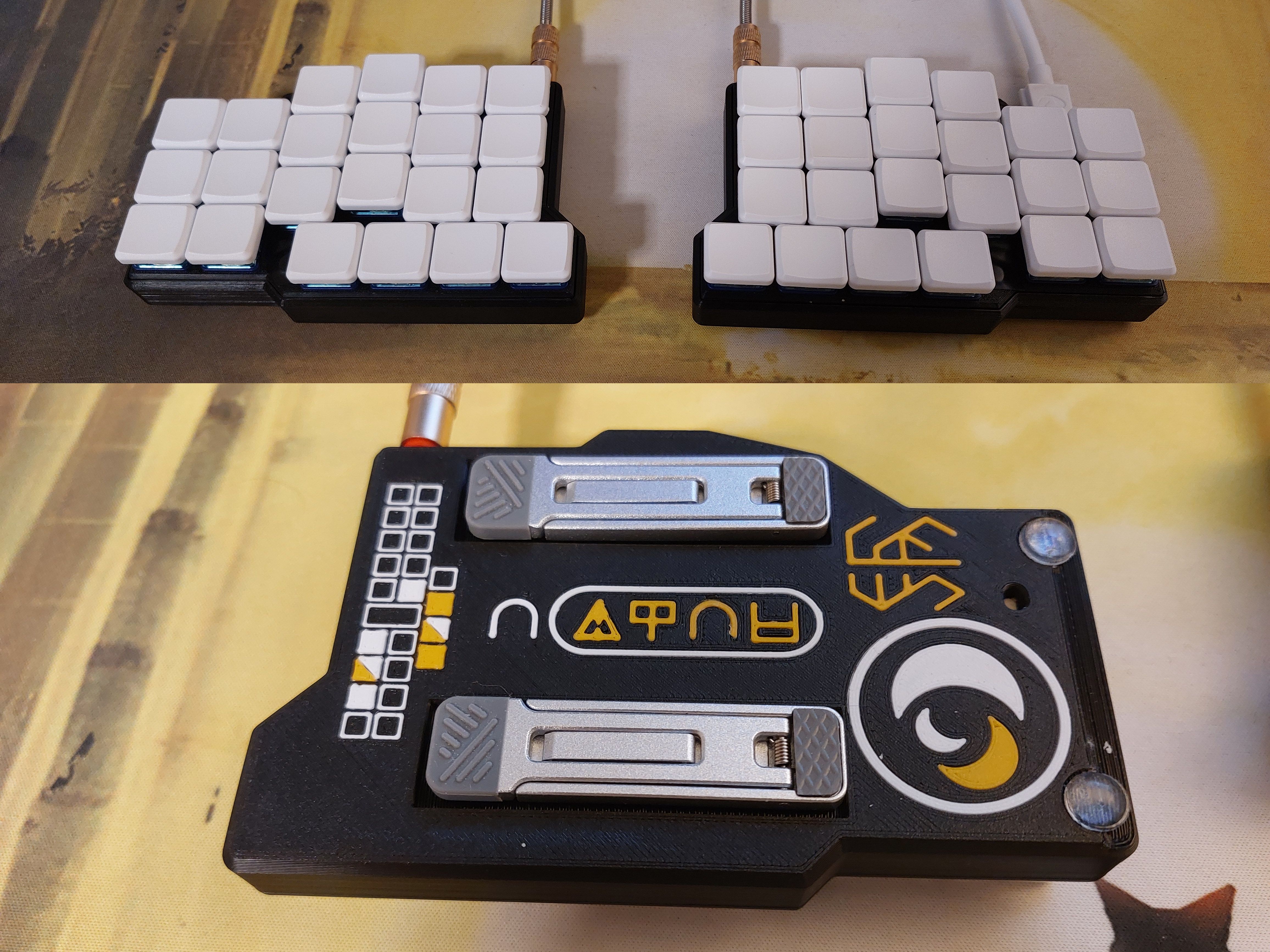
Disclaimers
- This is just a project I made for myself, so I didn't try and make it as easy as possible for others to reproduce or anything like that. The firmware is also extremely specific to my usecase (Colemak-DH with Swedish letters and a fuck-ton of esoteric custom features). I'll try my best to write instructions as clear as possible with the time I am willing to spend on this (as I find it unlikely that anyone will see this, and thus want to actually make the keyboard).
- The case itself is decently thick (at least for a 6x3 keyboard) at a bit more than 1 cm of thickness. This is because the RP2040-Zero and TRRS-jack is underneath the PCB, thus meaning that wires will need to be soldered from the PCB to the RP2040-Zero and TRRS-jack. For this I used AWG30 copper wire, but even with this thin wire it was still a pain in the ass to put the PCB into the case and screwing it down without any wires getting pinched.
- The case was designed to allow access to the reset switch of the RP2040-Zeros at the bottom. This turned out to be completely useless, as you can't enter the bootloader on an RP2040-Zero with that button, where you are actually supposed to hold down the boot button. I had this misconception from my previous keyboard I assembled which I thought used an MCU that functioned in the same way as an RP2040-Zero. If you want to you can edit the FreeCAD model to either remove the hole or move it to where the boot button is. In any case you won't need access to the boot button as you can hold down the bootmagic keys (discussed further down) to enter the bootloader.
- The tenting isn't super stable at high tenting angles. I use linear switches with an actuation force of 50g, and altough I probably hit the buttons quite a bit harder than necessary sometimes, the keyboard is pretty unstable at the highest tenting angle, and starts tipping pretty easily. When having it on the middle tenting setting it is way more stable, however that still tip a slight bit when pressing too hard. The lowest tenting setting however is stable. If you press really fucking hard then I suppose that it can start leaning a bit, but even with the force that I type with this does not ever happen.
Custom firmware features
(To see the key locations for the following features you will need to look in the source code, in qmk_firmware/keyboards/penor/keymaps/default.keymap.c, and look at the "ASCII-art" of the diffeenrt layers)
- A toggleable layer changing the main Colemak-DH layer to a QWERTY layer with the left side shifted one key to the right, so that it functions easier for games without having to rebind your keys.
- A layer that changes most of the keys to macros for common English words.
- Keys for controlling the mouse. If you quickly double-tap a direction the mouse will instantly move a ton in that direction, basically setting its position to the edge of the screen.
- Unicode mode, where you can type certain strings, which convert them to a unicode character using the Linux unicode input method of CONTROL+SHIFT+U. Pressing ESC cancels it, where as pressing SPACE or ENTER confirms which you have written. As an example, "pi" => "π".
- Recording and playing macros. Press the "record macro" key to start recording, press the "play macro" key to stop recording, or play the recording if it isn't currently recording, and press the "delay macro" button to add a 0.25 second pause when the macro gets to that recorded press during playback. The max amount of saved inputs in the macro is 256. Note that modifier keys count as two inputs; one from being pressed down, and once for being released. Note that most custom features like the word macros of common English word aren't supported in macro recordings, and won't play properly. The symbols from the symbol layer will however work.
- Key multiplication. Press the key to enter key multiplication mode. Type out a number, and then press any key, to make that key repeat that many times. Especially useful when wanting to go down n amount of rows in a document, or when wanting to replay the recorded macro a certain amount of times. Repeating a left/middle/right-click on the mouse will click the mouse at a speed of 30 CPS. If no number of repetition is specified then it will click at 30 CPS until canceled, which can be done by clicking with the mouse using the keyboard. The max amount of times a key can be multiplied is 100. If you tell it to repeat a mouse key a single time, then it will instead hold down that mouse key indefinitely until you press that mouse key again using the keyboard, which cancels it.
- A key for toggling usage of Plover (external software on the connected device). When entering and exiting the mode it will type out PHROLG to toggle Plover, where it will also toggle a layer with keys set up for Plover to work. In Plover the key bindings are tweaked a bit. Most of them are left on default, but some are changed. Since I don't know wich are default and not I will list all of the relevant bindings: 1234567890-= => #, \ => no-op, q => #, w => T-, e => P-, r => H-, t => *, y => *, u => -F, i => -P, o => -L, p => -T, [ => -D, ] => no-op, a => S-, s => K-, d => W-, f => R-, g => *, h => *, j => -R, k => -B, l => -G, ; => -S, ' => -Z, z => -D, x => -S, c => A-, v => O-, b => -Z, n => -E, m => -U, , => no-op, . => no-op, / => no-op, space => arpeggiate
How to flash firmware
- Before assembly: Hold down the boot button whilst plugging in the RP2040-Zero to your computer.
- After assembly: (this works for each individual side) hold down the key in the corner that is closest to the USB-port as you are plugging the USB in.
Once you have done either of these the RP2040-Zero should appear in your file browser. Open it and place your desired firmware (.uf2 file) there, which will then flash it.
Bill of materials
Note that this list will be for all the materials needed to create both halves of the keyboard
- 3D-printed parts. More info in the "3D-printing" section
- 1 TRRS cable
- 2 TRRS-jacks
- 2 RP2040-Zeros
- 44 THT diodes (1N4148)
- at least around 2-3 meters of loose wire (AWG30 worked pretty well for me)
- 44 Kailh Choc switches and keycaps. V1 switches are definitely compatible, but I don't know if V2 switches are or not. It's not impossible though, you would have to check the KiCad project or the gerber file of the PCB.
- 4 tenting feet. Not sure what they are called but I at least bought mine from here https://keyboard-hoarders.com/products/tenting-feet
- 4 anti-slip pads. The one included with the tenting feet from the link above are sadly too large, so I went with ones that I specifically had laying around. They were around 2.7 mm tall, and 8.5 mm in diameter. If they are a bit taller then that is fine, but its best if it isn't shorter. The diameter should probably at max be 9 mm.
- 8 M4 nuts
- 4 10 mm long M4 bolts
- 4 roughly 7 mm long M4 bolts. I just bought 10 mm long ones and cut them down extremely sloppily with a metal saw. As long as they are short enough that they can be screwed down where the PCB lies to the hole in the case without hitting the bottom, and whilst still being long enough to lock with the nut in there then its good. I don't know if this is part of the ISO standard or not, but the bolts should be the type that has a circular head that you screw down with a screwdriver. The diameter of the head can't be more than 8 mm.
- 2 PCB plates. The single design of the PCB in this repo works for both for the left and right side of the keyboard, as you just have to flip it around. Order the PCB using the gerber file in this repo and make sure that its thickness is 1.6 mm (this is the most common PCB thickness).
3D-printing
If you have a Creality Ender S1 (or if you think that the GCODE will still be compatible) and are using PLA or some other plastic that is printable at 200C then you don't have to worry about any of the slicing, and can just print all of the GCODE files in case/gcode/. Keep in mind the points where the print pauses where you should add nuts, and also how the printing of the logos underneath the left half should be done in a specific way. Read the instructions underneath that explains how to slice the 3D models as it explains how stuff should be done and whatnot idk.
The following files will be found in case/models/
- If you want the diode to be easier to fold for the PCB you can slice and print the "diode_folder.step". It is honestly very finicky though as I designed it to be so small.
- Slice and print "PENOR_plate_(left, but mirrorable).step", and then slice and print it again but with the model mirrored (should be possible in pretty much all slicing software... I think at least).
- Slice and print "PENOR_TRRS_holder_left.step" and "PENOR_MCU_holder_left.step", and then do it again but with both models mirrored. Note that the TRRS model can be printed without any support by making the overhanging part lay flat on the bed. The MCU holder model should be oriented so that the slight overhanging part is on top (the same orientation that it will have in the assembly). This of course requires some support material under the overhang, but support material isn't needed anywhere else for that model.
- Mirror "PENOR_right_main_UNMIRRORED.step" as you slice it, and make sure that it pauses on the layer just before the hole for the nut where the PCB will be screwed in gets covered, where you should add nuts into the two holes before resuming the print. Also make sure to add support material where the anti-slip pads will be. If you also aren't sure if the bridge done where the tenting feet will sit will be able to be printed without drooping then you can also make a line of support material along the center of the hole.
- Slice and print "PENOR_left_white.step", "PENOR_left_orange.step", and "PENOR_left_main.step" right after each other as shown in this video https://youtu.be/m_SXRGGoTQo, to make it possible to print the logos at the bottom with two different colors from the color used for the main part of the case. Remember to also add the pause for the nuts and the necessary cupport material on the left half of the case too!
Assembly instructions
- Before assembling anything you should already flash the firmware to BOTH of your RP2040-Zeros, as it contains logic for allowing to enter the bootloader without the usage of the boot button which won't be acessible in the finished assembly. Just hold down the boot button whilst plugging it into your computer, and it should appear in your file manager. Place the .uf2 file from this repo (or compile the firmware yourself) into the RP2040-Zeros. If your RP2040-Zeros has "perferations" on the edges from when it was snapped of from a larger board then you should sand these down so that the edges of the board are flat, as otherwise they won't fit properly in the case.
- Solder all the diodes to the PCB. Remember to look at the icons on the PCB that specify what direction the diodes should have so that you don't acidentally assemble some in the wrong direction, as sometimes the direction is different from what you might expect (almost all point downwards, however a few point up). Once soldered, clip the legs so that they are pretty short, so that they fit for the next step.
- On the side that has the leg joints, put the 3D-printed switch plate on the PCB, and put all of the switches through the switch plate and PCB, and then solder all of the switches to the PCB.
- Solder loose wires to every hole on the PCB that is labeled as "row n" and "col n" (where n is a number). In total you should have 10 loose wires. The longer they are, the more you will want to shoot yourself when trying to assemble the plate with the case without any wires being in the way, however if they are too short then everything will be extremely tight. I recommend making the wires furthest away from where the RP2040-Zero will be in the case be around 10 cm, where the closest ones can be around 6 cm or so. For the left half I made ALL of the wires 15 cm long and the walls in my room almost became red.
- Solder wires from the RP2040-Zero to the TRRS-jack. Remember to look at how the RP2040-Zero will lay in the case to ensure that you solder the wires onto the pins in ways that the wires will actually be able to lay in so that they don't have to make any really sharp turns, concidering how there is a wall directly next to the RP2040-Zero on one side (don't forget that the side the wall is on changes for each half of the keyboard!). You need three wires for this, which I recommend making around 10 cm. Technically the legs you decide to use for the TRRS-jack doesn't matter as long as you do the same for both halves, but I'll say which ones I used. Remember to try and solder it to the legs so that the solder is on the inside of the legs and not the outside, so that the jack can lay flat without the solder being in the way. Also make note of how the jacks will sit in the case, so that you solder the wires to go in the correct direction so that they don't have to bend sharply.
- Solder a wire from the GND pin to the leg that is alone on its side.
- Solder a second wire from the 3V3 pin to the leg that is the closest to the leg you previously soldered to.
- Solder the last wire from pin 0 to the leg that is next to the second leg you soldered to.
- If you are assembling the left half (and ONLY if it is the left half), solder a short wire from 3V3 to pin 29. This is to make it able to tell that it is the left half of the keyboard automatically.
- Solder all of the wires onto the RP2040-Zero. Remember to concider the walls to make the wires not have to make any really sharp turns by the pins. Also remember to concider how the part that will hold down the RP2040-Zero will cover up the pins at the bottom, which will thus also to some extent be like a wall that needs to be router around.
- col0 -> pin 2
- col1 -> pin 3
- col2 -> pin 4
- col3 -> pin 5
- col4 -> pin 6
- col5 -> pin 7
- row0 -> pin 15
- row1 -> pin 26
- row2 -> pin 27
- row3 -> pin 28
- Put the TRRS-jack by its hole in the case. Add a nut to the hole next to it, and use a bolt to screw the small 3D-printed part that holds it in place. Then put the RP2040-Zero where it should be in the case, add a nut to the 3D-printed part that holds it down, and fasten it with a bolt. If you have no clue which parts are supposed to be used for this then you can look in the FreeCAD model in this repo and see the location of all the parts.
- Put the PCB onto the case, making sure that no wires are getting pinched between the PCB and the case. You will most likely need some long and slim object like a chopstick to try and nudge wires away from areas that the PCB will lay on as you put the PCB on. Once there is no wobble, or at least extremely minimal wobble, you can screw the two bolts into the holes in the PCB. If you have printed the case in black like shown in the image at the top of this file then you can optionally put electrical tape onto the screw heads. It does't look absolutely perfect, but it does make it look way neater than seeing two big-ass silvery bolt heads between your keys.
- Do a happy little dance (IMPORTANT! Only do this if the keyboard works correctly).
Compiling firmwre (not needed if you just use the qmk_firmware/keyboards/penor/penor_default.uf2 file)
-
Use QMK Firmware 0.23.7. Different versions might work, however it should for sure work on this version.
-
copy over the directory qmk_firmware/... to the directory where your qmk_firmware is located, making it so that the penor/... is inside of your qmk_firmware/keyboards.
-
Make sure that your working directory in the terminal is the qmk_firmware directory, and then run the command
make penor:default


 theBaksoBoy/penor-keyboard1


