2 layers240 × 125 mm
Controller
Technariumas/smalsiukas
The conversion of a forklift truck to a line following robot.
277 partsApache-2.0

 Technariumas/smalsiukas
The conversion of a forklift truck to a line following robot.
Line interface is an open-source printed circuit board by Technariumas, from the Technariumas/smalsiukas repository on GitHub, published under the Apache-2.0 licence. It is a 2-layer board of 52 × 49 mm with 35 parts on 25 nets, routed with 190 tracks and 18 vias.
It is built around the ATTINY441-SSU, SN65HVD72D and LM7805CT, with the NDT2955 among its other parts. Its parts include 9 capacitors, 8 resistors, 6 diodes, 3 ICs and 3 connectors. It belongs with the robots and motor control and interfaces and adapters boards and the AVR (ATmega, ATtiny) boards of this library.


The conversion of a forklift trucks to a line following robot.
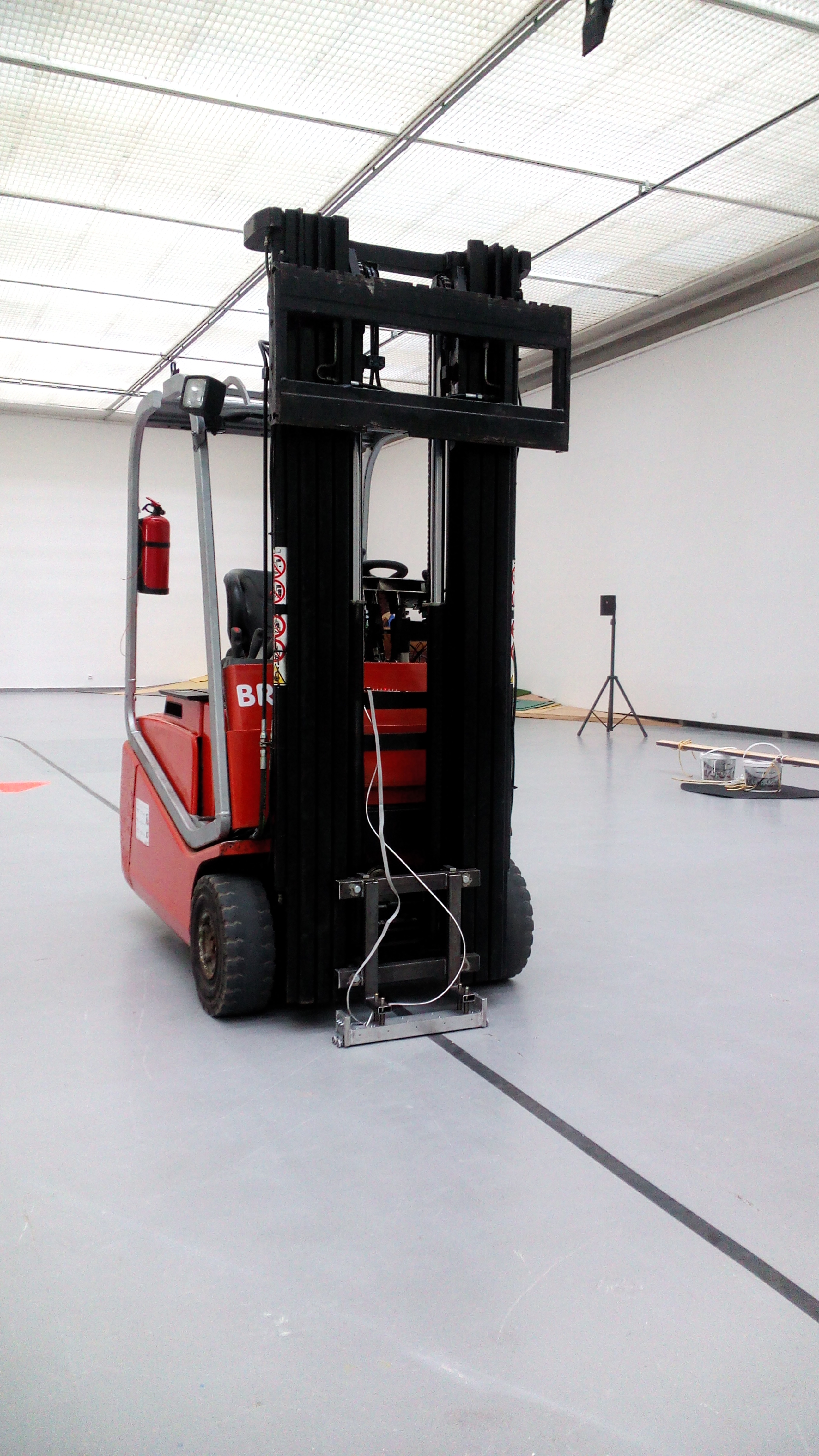
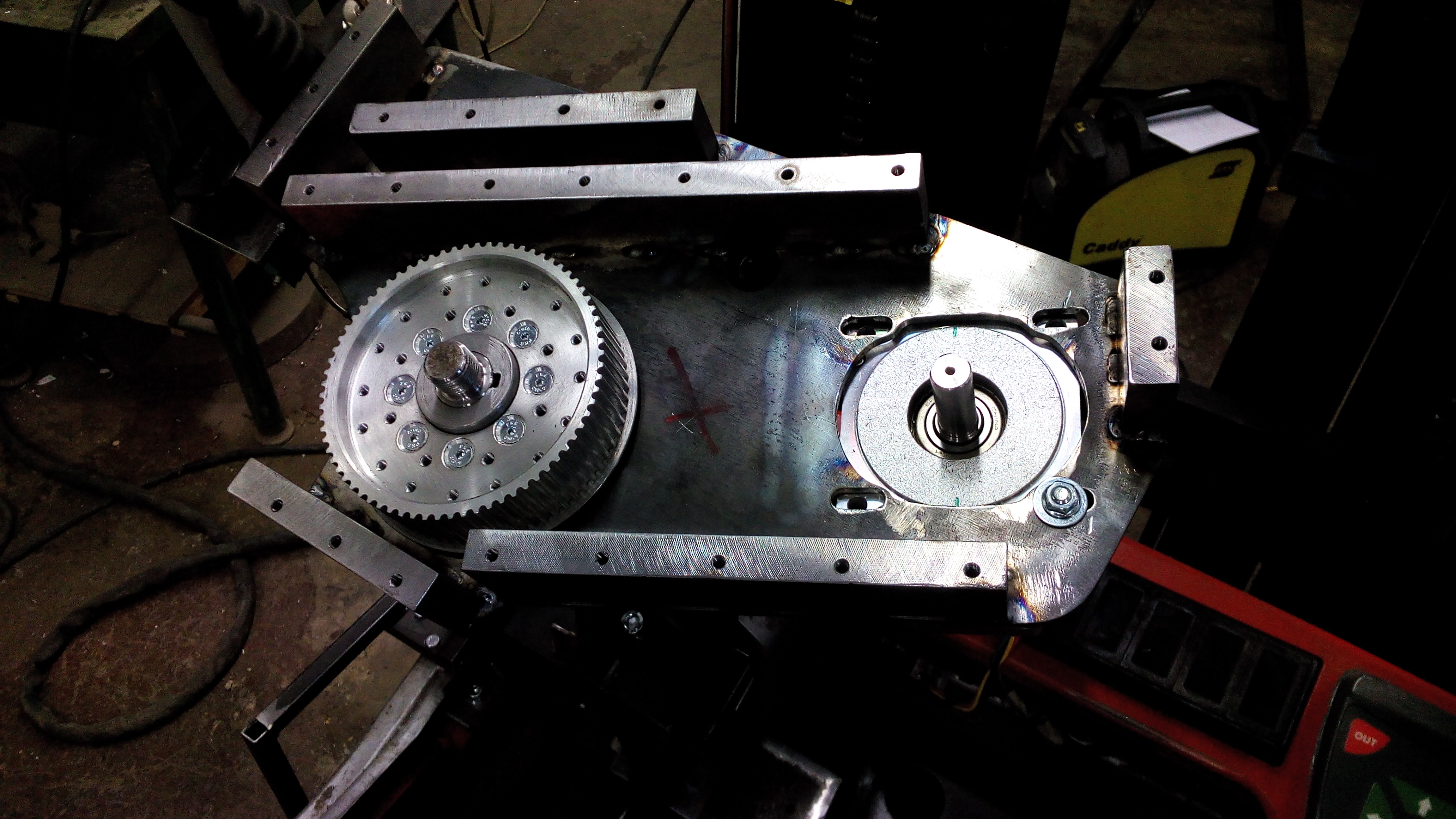
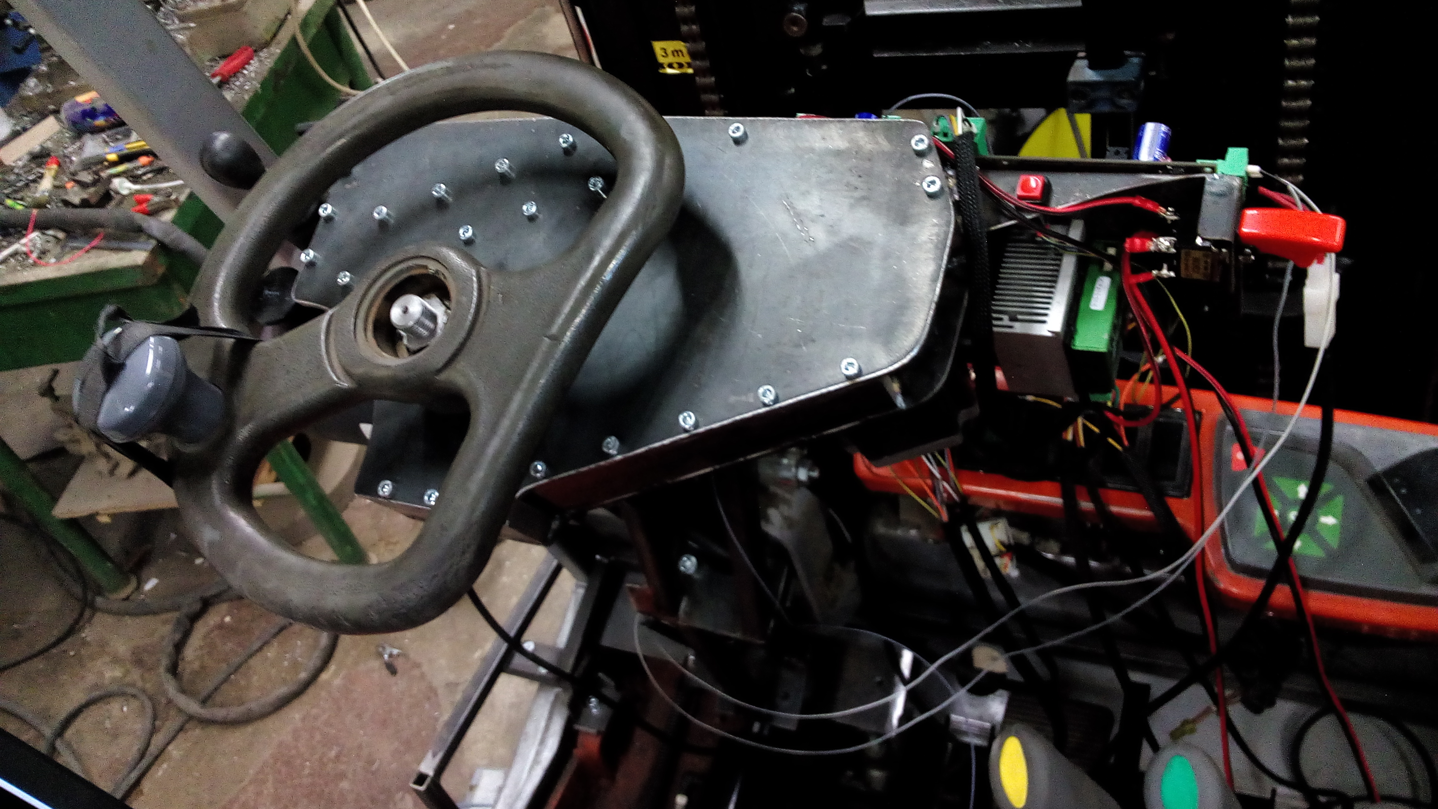
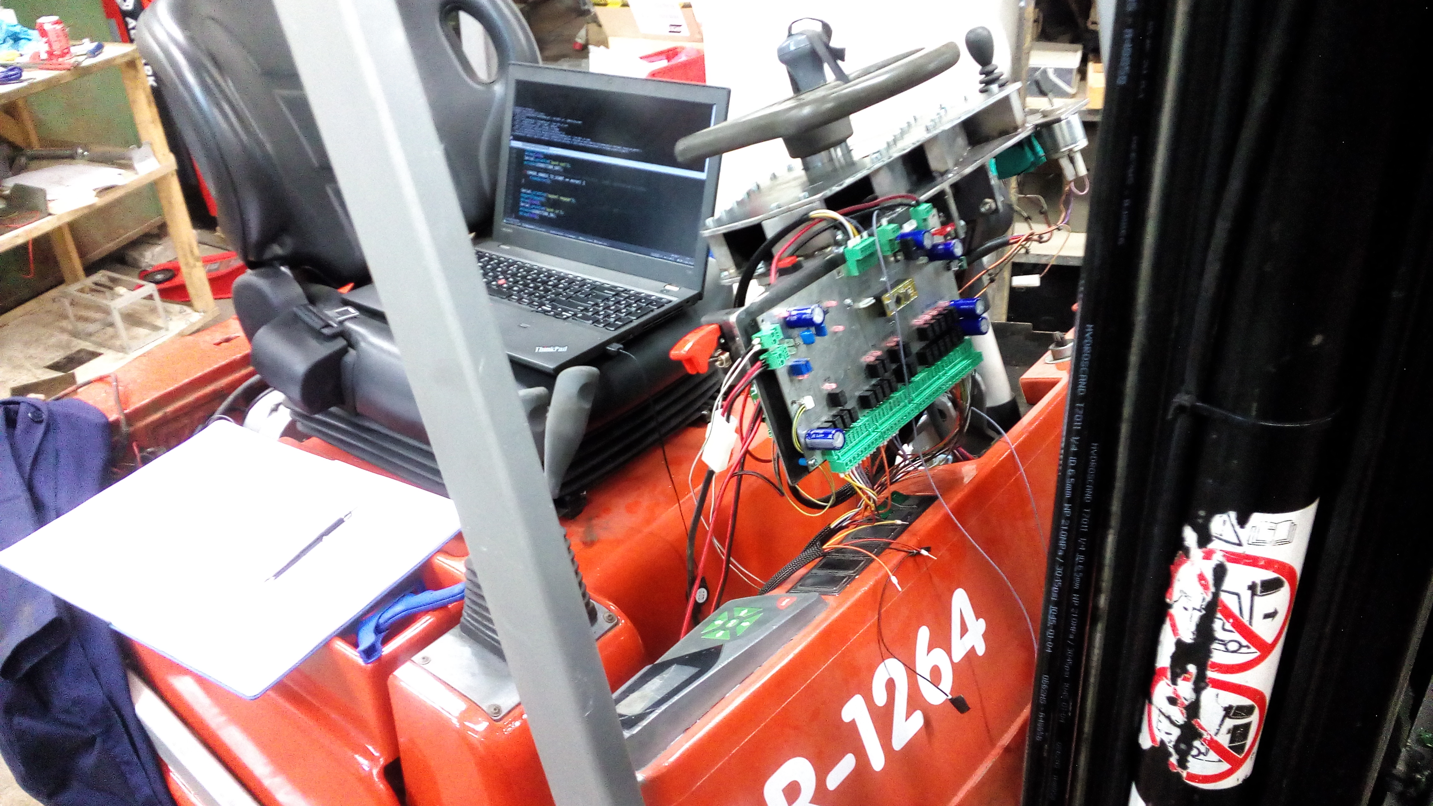
A file set related to conversion of BT C3E C4E forklift truck and Linde lifter to a line-following robot for an art installation of Robertas Narkus "Träger"
| Qty | Value | Footprint | References |
|---|---|---|---|
| 6 | 10k | Resistors_SMD:R_0603 | R2, R3, R4, R6, R9, R10 |
| 4 | 1u | Capacitors_SMD:C_0603 | C1, C4, C7, C9 |
| 4 | Mounting_Hole | Mounting_Holes:MountingHole_3.2mm_M3 | MK1, MK2, MK3, MK4 |
| 2 | 18p | Capacitors_SMD:C_0603 | C6, C8 |
| 2 | 1u | Capacitors_SMD:C_1210_HandSoldering | C2, C5 |
| 2 | GREEN | LEDs:LED_0603 | D4, D6 |
| 1 | 10 | Resistors_SMD:R_2512 | R1 |
| 1 | 15V | Diodes_SMD:SOD-123 | D3 |
| 1 | 16MHz | Crystals:Crystal_HC49-SD_SMD | X1 |
| 1 | 330 | Resistors_SMD:R_0603 | R8 |
| 1 | 60V | Diodes_SMD:D_SMB_Handsoldering | D2 |
| 1 | ATTINY441-SSU | Housings_SOIC:SOIC-14_3.9x8.7mm_Pitch1.27mm | IC1 |
| 1 | CONN_01X04 | Connectors_JST:JST_EH_B04B-EH-A_04x2.50mm_Straight | P2 |
| 1 | CONN_01X06 | Pin_Headers:Pin_Header_Straight_1x06_Pitch2.54mm | J1 |
| 1 | CONN_02X03 | Pin_Headers:Pin_Header_Straight_2x03_Pitch2.54mm | P1 |
| 1 | CP1 | Capacitors_ThroughHole:CP_Radial_D8.0mm_P3.50mm | C3 |
| 1 | D | Diodes_SMD:D_SOD-123 | D7 |
| 1 | D_TVS_ALT | Diodes_SMD:Diode-SMC_Handsoldering | D1 |
| 1 | LM7805CT | TO_SOT_Packages_THT:TO-220_Horizontal | U1 |
| 1 | NDT2955 | TO_SOT_Packages_SMD:TO-252-2Lead | Q1 |
| 1 | SN65HVD72 | Housings_SOIC:SOIC-8_3.9x4.9mm_Pitch1.27mm | U2 |
Technariumas/smalsiukas
The conversion of a forklift truck to a line following robot.

Technariumas/smalsiukas
The conversion of a forklift truck to a line following robot.

Technariumas/smalsiukas
The conversion of a forklift truck to a line following robot.

Miceuz/rs485-moist-sensor
Digital (RS485 - based) soil moisture and temperature sensor

Miceuz/rs485-breakout
A tiny development board to quickly prototype RS485/Modbus devices

punkfab/pcb-corpus
235 real KiCad boards from open-source hardware repositories, prepared as a placement and routing benchmark

zmaker/arduino_cookbook
gli sketch del nuovo progetto Arduino Cookbook e dei video di YouTube

matoushybl/sm4
This repository contains everything related to the SM4 Stepper motor controller project.

Dima-Shlenkevitch/Tactile-On-Off-Power-Switch
This project is about replacing a mechanical switch with tactile push button and latch circuit

karimf1/rover-panel-pcb
This repository is continuation of rover panel repo. Power panel PCB layout is implemented in KiCAD based of AutoCAD version of rover panel .

aspdac-submission-pcb-layout/PCB-Layout-Framework
This repository has been prepared from the original. Some care has been taken to remove the names of the authors.
It measures 52 × 49 mm and has 2 copper layers, 1.6 mm thick.
35 parts, built around the ATTINY441-SSU, SN65HVD72D, LM7805CT and NDT2955. The full list of its parts is on this page, with links to each part's symbol and footprint where PCBKit's library has them.
From the Technariumas/smalsiukas repository on GitHub, at the commit this page was made from: the board is line-interface/line-interface.kicad_pcb. PCBKit opens the board in the browser, with nothing to install.
Its repository publishes it under the Apache-2.0 licence: you may reuse it on that licence's terms (keep the author's notice, and for a copyleft licence share your changes alike).