2 layers65 × 56 mm

 techmoocher/kitsujikan
A little Pomodoro timer (my first hardware project!!!)
Kitsujikan is an open-source printed circuit board by techmoocher, from the techmoocher/kitsujikan repository on GitHub, published under the MIT licence. It is a 2-layer board of 65 × 90 mm with 23 parts on 22 nets, routed with 94 tracks and 4 vias.
Its parts include 6 switches, 5 resistors, 3 connectors, 1 capacitor and 1 IC. It belongs with the ESP32 and RISC-V boards of this library.
A rechargeable, pocket-sized Pomodoro timer with an OLED display and colour-coded buttons, designed for Hack Club's Half-Life 10-week hardware challenge.
| Front | Back |
|---|---|
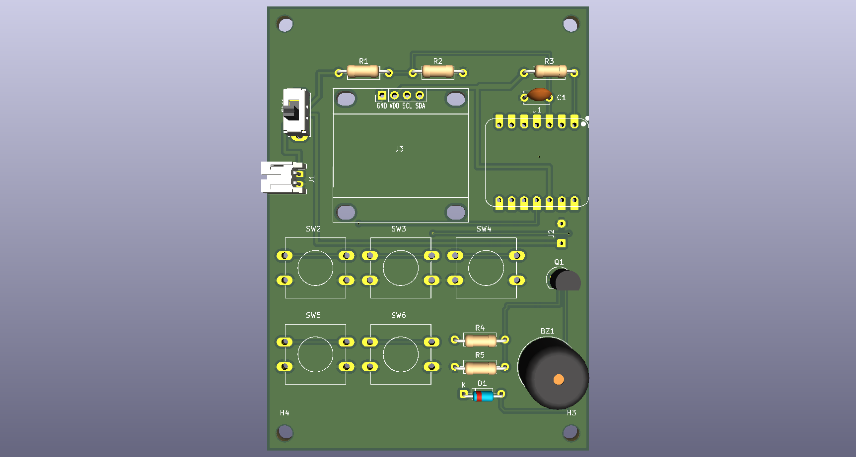 | 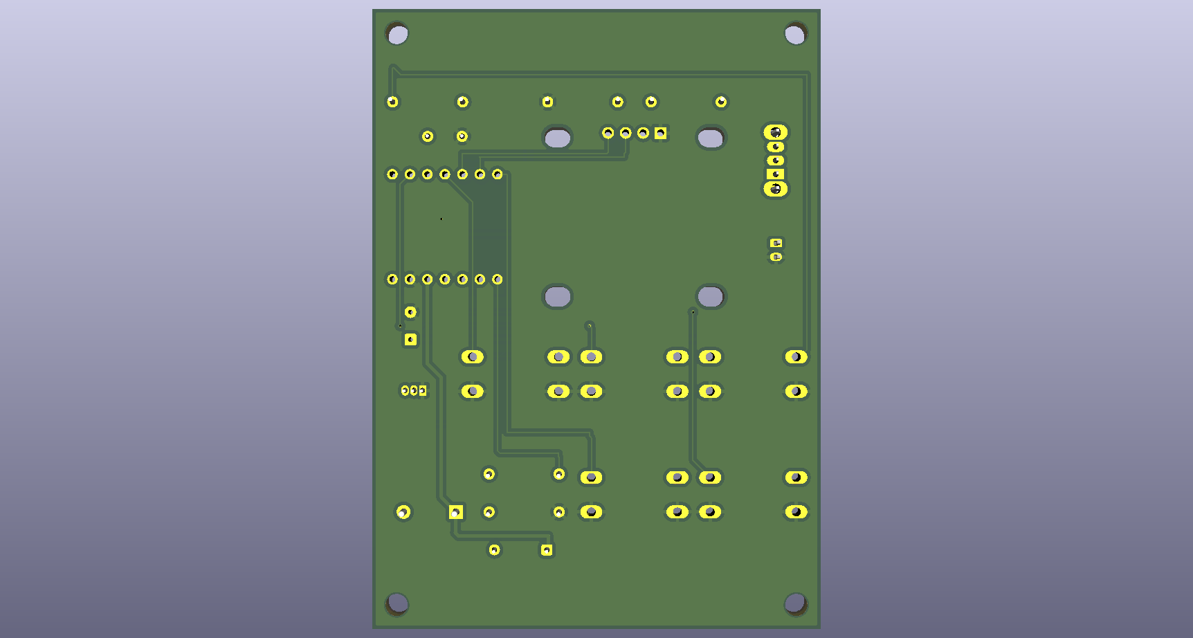 |
HH:MM:SS. Hours are hidden when zero, and minutes and seconds always show two digits.| Power | 3.7 V LiPo (JST-PH), slide switch, 2 × 200 kΩ battery-sense divider | | PCB | 2 layers, 65 × 90 mm, all through-hole parts |
| XIAO pin | GPIO | Connected to | Why this pin |
|---|---|---|---|
| D0 | 2 | 30-min button (+10 kΩ pull-up) | Can wake from deep sleep; it's a strapping pin, so the pull-up holds it high at boot |
| D1 | 3 | 60-min button | Can wake from deep sleep |
| D2 / A2 | 4 | Battery voltage (divider midpoint) | Calibrated ADC1 channel |
| D3 | 5 | 90-min button | Can wake from deep sleep; its ADC2 channel is unreliable anyway |
| D4 / D5 | 6 / 7 | I2C SDA / SCL (OLED) | Default I2C pins |
| D6 | 21 | Red No/Pause button | Not a strapping pin |
| D7 | 20 | Buzzer transistor | Input at boot, so the buzzer stays quiet |
| D10 | 10 | Green OK button | General purpose |
| D8, D9 | 8, 9 | Unused | Strapping pins (D9 is the BOOT button) |
PCB/                 KiCad 10 project (schematic + board)
PCB/libs/            Symbol, footprint and 3D libraries used by the project
PCB/production/      Gerber and drill files for manufacturing
renders/             3D renders of the board
Firmware/            Arduino firmware for the XIAO ESP32-C3
kitsujikan_BOM.csv Bill of materials with sources and estimated pricesThe full list with links is in kitsujikan_BOM.csv. Summary:
| Qty | Part | Source |
|---|---|---|
| 1 | Seeed Studio XIAO ESP32-C3 | Seeed Studio |
| 1 | 0.96" SSD1306 I2C OLED (pins: GND, VCC, SCL, SDA) | Amazon |
| 5 | 12×12 mm tactile switches with coloured caps | Amazon |
| 1 | C&K OS102011MS2QN1 slide switch | LCSC / DigiKey |
| 1 | JST-PH 2-pin side-entry socket (S2B-PH-K-S) | LCSC / DigiKey |
| 1 | 3.7 V ~500 mAh LiPo with protection circuit, JST-PH plug | Amazon |
| 1 | Passive buzzer, 12 mm | Amazon |
| 1 | 2N3904 transistor, 1N4148 diode | Amazon |
| 5 | Resistors: 2 × 200 kΩ, 2 × 10 kΩ, 1 × 1 kΩ | Amazon |
| 1 | 100 nF ceramic capacitor | Amazon |
| — | Female pin headers (1×7 ×2, 1×4 ×1), thin wire | Amazon |
| 5 | PCBs | JLCPCB |
Prices in the CSV are rough estimates. Many Amazon items come in multi-packs, so the first build costs more than the parts on one board.
PCB/production/.Arduino (C++) for the ESP32-C3, in Firmware/. It covers the timer state machine, debounced buttons (tap / hold), buzzer melodies, the OLED screens, battery percentage, and deep sleep with wake-on-button. Build steps and controls are in Firmware/README.md. The timer logic has laptop unit tests in Firmware/test/.
This project is released under the MIT License. Third-party libraries in PCB/libs/ remain under their original authors' licenses.
| Qty | Value | Footprint | References |
|---|---|---|---|
| 4 | MountingHole | MountingHole:MountingHole_3.2mm_M3 | H1, H2, H3, H4 |
| 2 | 10k | Resistor_THT:R_Axial_DIN0207_L6.3mm_D2.5mm_P10.16mm_Horizontal | R3, R5 |
| 2 | 200k | Resistor_THT:R_Axial_DIN0207_L6.3mm_D2.5mm_P10.16mm_Horizontal | R1, R2 |
| 1 | 100nF | Capacitor_THT:C_Disc_D5.0mm_W2.5mm_P5.00mm | C1 |
| 1 | 1N4148 | Diode_THT:D_DO-35_SOD27_P7.62mm_Horizontal | D1 |
| 1 | 1k | Resistor_THT:R_Axial_DIN0207_L6.3mm_D2.5mm_P10.16mm_Horizontal | R4 |
| 1 | 2N3904 | Package_TO_SOT_THT:TO-92_Inline | Q1 |
| 1 | 30min | Button_Switch_THT:SW_PUSH-12mm | SW2 |
| 1 | 60min | Button_Switch_THT:SW_PUSH-12mm | SW3 |
| 1 | 90min | Button_Switch_THT:SW_PUSH-12mm | SW4 |
| 1 | Battery | Connector_JST:JST_PH_S2B-PH-K_1x02_P2.00mm_Horizontal | J1 |
| 1 | Buzzer_passive | Buzzer_Beeper:Buzzer_12x9.5RM7.6 | BZ1 |
| 1 | NO_RED | Button_Switch_THT:SW_PUSH-12mm | SW6 |
| 1 | OK_GREEN | Button_Switch_THT:SW_PUSH-12mm | SW5 |
| 1 | OLED_SSD1306 | Imported Parts:Display_128x64_096_I2C | J3 |
| 1 | Power | Button_Switch_THT:SW_Slide_SPDT_Straight_CK_OS102011MS2Q | SW1 |
| 1 | XIAO-ESP32-C3-SMD | Imported Parts:XIAO-ESP32-C6-DIP | U1 |
| 1 | XIAO_BAT | Connector_Wire:SolderWire-0.15sqmm_1x02_P4mm_D0.5mm_OD1.5mm | J2 |
It measures 65 × 90 mm and has 2 copper layers, 1.6 mm thick.
23 parts. The full list of its parts is on this page, with links to each part's symbol and footprint where PCBKit's library has them.
From the techmoocher/kitsujikan repository on GitHub, at the commit this page was made from: the board is PCB/kitsujikan.kicad_pcb and its schematic PCB/kitsujikan.kicad_sch. PCBKit opens the board in the browser, with nothing to install.
Its repository publishes it under the MIT licence: you may reuse it on that licence's terms (keep the author's notice, and for a copyleft licence share your changes alike).

google/mozc-devices
Circuit diagrams and firmware source code for Gboard DIY keyboards


Duet3D/Duet-2-Hardware
The KiCAD source for the Duet 3d printer controller see www.duet3d.com