2 layers73.2 × 61.6 mm
ZX Diagnostic 2021
tebl/ZX-Interface-2.021
An old-school remake of the ZX Interface 2 with some modern tweaks - mainly by integrating bank switching into the interface itself.
30 parts32
 tebl/ZX-Interface-2.02132
An old-school remake of the ZX Interface 2 with some modern tweaks - mainly by integrating bank switching into the interface itself. Everything done with basic logic chips and components, no magic black boxes to be found anywhere!
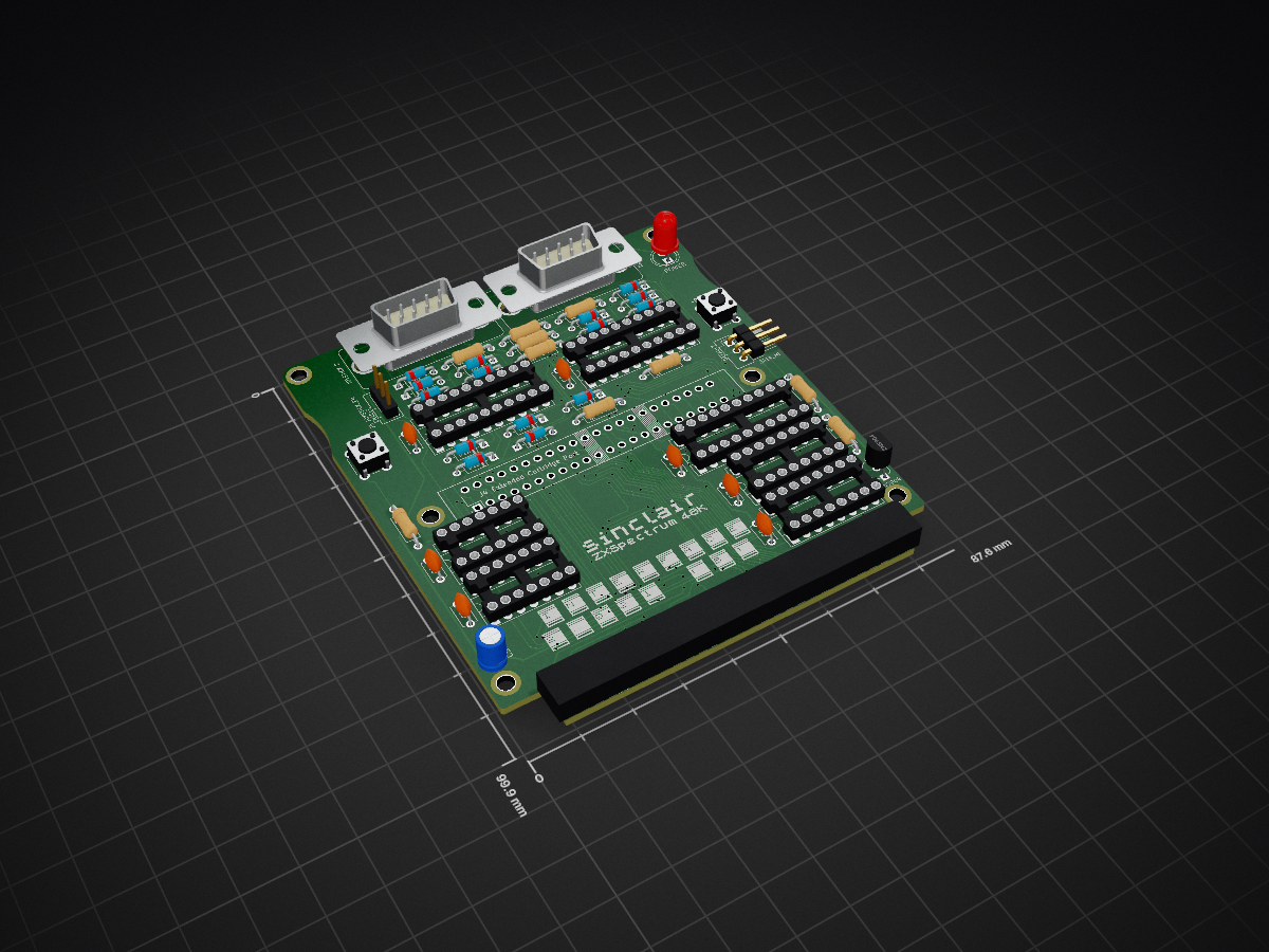
ZX Interface 2021 is an open-source printed circuit board by tebl, from the tebl/ZX-Interface-2.021 repository on GitHub. It is a 2-layer board of 118.1 × 99.9 mm with 58 parts on 84 nets, routed with 1,188 tracks and 137 vias.
It is built around the 74LS245SC, 74LS04PC and 74LS27P-E, with the 74LS273PC among its other parts. Its parts include 16 diodes, 10 resistors, 8 capacitors, 7 ICs and 5 connectors. It belongs with the retro computing and games and interfaces and adapters boards of this library.


The ZX Diagnostic 2.021, simply referred to as the diagnostic cartridge for the remainder of this document, has been specially made to work with the diagnostic firmware developed by Brendan Alford. Part of the hardware used within the ZX Interface 2.021 has been designed to be functionally similar to other diagnostic cartridges, in particular the bank switching scheme and the way the cartridge can be disabled by the computer was based on the following blog post.


The rest of the functionality needed to serve as a diagnostic cartridge has been added to the ZX Diagnostic 2.021, apart from being a 16K cartridge there is an 8bit latch that will be used to output diagnostic status to the LEDs. The LEDs will allow some additional feedback to show that the computer is somewhat functional, even when there there is no image. Compared to the ZX Cartridge 2.021, this only supports a single ROM chip with sizes ranging ranging from 27C128 up to 27C512.

Note that there are various faceplates available for the cartridges, these complete the look of the cartridge as well as help them balance on top of the interface. Check out the faceplates section for an overview over the ones that have been made available, also see PCBWay shared projects.
Building the unit assumes you have at least minor experience soldering things together, recommended is at least a soldering station with adjustable temperature to get started - usually you'll want some 60/40 solder tin (if you can get that where you live). Given that we're going to be flashing data onto EPROM chips, you'll need an EPROM programmer suitable for this task - the one I'm using is a MiniPro TL866CS and so far it's surpassed my expectations for such a reasonably priced device. If you are going to use EPROM chips you will need an EPROM ereaser as well, but read on - you might not need that depending on the chips you purchase.
With the equipment sorted, now comes the shopping - so head on over to the BOM-section for some information on what you need. Note that with sites such as ebay, AliExpress and similar sites that sell cheap chinese components, you'll need to treat these as a suggested search term and look for something that matches the gallery pictures.
You'll need to order some EPROM chips as well. As previously mentioned, you can use anything from 27C128 up to 27C512 chips. One specific chip I can recommend looking for is the W27C512 chip as that is actually an EEPROM with the same pin layout, meaning you won't need the previously mentioned EPROM ereaser. The price difference is negligible unless you're going to make a lot of them.
The construction of this unit should be fairly straight-forward, just take your time in order to make sure everything goes into place - more or less straight. I usually recommend starting by having a good look at the PCBs, try to figure out where all of the listed components go and in which orientation they go (all of this should be clearly marked on the silkscreen).

The last version I built is the one shown above, and going forward I usually try installing components sorted by physical - going from the smallest to the largest. The reason for this is that you want to be able to solder most of it into place before it starts wobbling on your desk, for the ZX Diagnostic 2.021 this means saving all of those LEDs until last.

At this point we've soldered in all of the resistors, but take note that one of them will have a different resistor value from the others. There are two solder jumpers on the cartridge, these are clearly labelled A14 and A15 with pin 1 identifiable as the square pad. You need to add some solder to bridge between two of the pins, this is dependent on the type of (E)EPROM you are going to install into the socket marked U1 - see the table below for all supported ROM types.
| (E)EPROM | A15 | A14 |
|---|---|---|
| 27C512 | 1-2 | 1-2 |
| 27C256 | 2-3 | 1-2 |
| 27C128 | 2-3 | 2-3 |
Next is the single right-angle pin header that is used to enable the LEDs at the top - to get that on straight, just solder on one of the pins, then reheat and adjust the position before soldering in the final pin. Alternatively you could also just solder a wire across the two pins to keep them permanently disabled, but this isn't recommended unless you know that the cartridge will only ever be used for diagnostic purposes.


At this point, we've just gone ahead and added both the sockets, making sure to match the indent in the sockets with the symbols on the silkscreen - this means that pin 1 of the ICs is at the top-right corner of the sockets. Solder in the corners of the sockets first, gently reheat one pin at a time and press the socket firmly against board to avoid accidentally soldering it in at an angle (removing a socket is a lot harder than it is to solder it in).

The ceramic capacitors do not have a polarity, so we can just solder them into place without issues. Personally I tend to ensure that the values printed on them is visible from the outside, but that's just nit-picking.

The last thing we're going to solder into place is the LEDs, but as they need to line up with the holes in the faceplate we'll need to take care when doing so to ensure that they're straight. Before we get that far though, we'll need to say a few words about the LEDs themselves - soldering them in the wrong way will ensure that won't work. I can never remember what the proper names of each of the pins are, so I'll just pass along the way I do it - essentially the longest lead goes into the round hole. The shorter lead, big surprise here, goes into the other hole.
Just do one row at a time, soldering in just one of the pins - then reheat and push the LED flush against the board (no matter how hard I try, they're never straight enough on the first try). When you're sure that all of them line up correctly, only then do you solder in the other pin.
The last step that we need to do is simply inserting the chips, as has been pictured so far I've soldered the jumpers according to the settings for a 27C512-type of ROM - in this case using the W27C512 EEPROM. Make sure that you insert the chips in the correct orientation, the indent will be to the right. I put together a separate document that goes into flashing the (E)EROMs, the diagnostic firmware can be downloaded from the authors github-repository (it'll be called testrom.bin, this file can only be downloaded as part of the releases). Then add a jumper cap to enable the LEDs.
There isn't all that much that can be said for assembling the unit, chances are you've already finished the entire thing by this point. The only remaining step would just be to add a faceplate, it helps keep the cartridge from flopping around in the cartridge slot while also adding quite a bit of visual flair to it.
The faceplate is just a simple PCB, the suggested way of attaching it is by using components found in cheap M3 nylon hex kits. It will look at its best when using an 8mm nylon hex standoff (F-F), then adding screws from both sides. If, on the other hand, you want to stay within the kit - then I suggest using the 8mm M-F standoffs, add M3 nuts on the bottom and snip off the remaining part of the nylon screw that'll poke through. Add screws on top. Your success on this step will be dependent on how straight you soldered on the LEDs, so reheat and adjust any that fails to line up with the holes in the faceplate.
I shouldn't have to say it at this point, but I'll do so anyway - cartridges are not memory cards, plugging them in or unplugging them while the system is powered on will KILL your equipment. With that out of the way, just plug the cartridge into the slot and then apply power to see if whatever you put into the first 16K of the (E)EPROM starts up as expected. I put together a separate document that goes into flashing the (E)EROMs.
The ZX Spectrum doesn't actually have any knowledge of any of the bank switching logic installed on the interface, in fact the ROM in your computer will be completely disabled when any cartridge is inserted into the interface. Given that this is meant to be a diagnostic cartridge, I'll assume you've gone ahead and used Brendan Alfords diagnostic firmware as the first 16K bank - it should start automatically and run through the tests as it should.
Unless you hold down any of the buttons when starting the computer, it should run through all of the tests once and then - after a countdown - page out the diagnostic ROM and return you to the standard ZX Spectrums basic. This is normal, it just shows that the entire system for the most part works as it should. At this point you might want to try out any of the images put into the other ROM banks, I've added some more details on what to do next to the bank_switching document.
You can control the LEDs directly from basic if you want to, they're placed on port 63 and by using the OUT command you can control them. All you need to do is write a value to have the LEDs display it in binary, for example the following to separately light up each row of LEDs:
OUT 63, 85
OUT 63, 170
You know you want to program an LED chaser now, you know you do! In case you're not old enough, they're what made KITT cool and the Cylons scary.
The supplied KiCad files should be sufficient as both a schematic and as a starting point for ordering PCBs (basically you could just zip the contents of the export folder and upload that on a fabrication site), the schematic is also available in PDF-format and this is what you'll need to print and work your way through this things don't work as expected after assembly.
Most parts should be easy to get a hold of from your favourite local electronic component shop, but given that I don't have access to such shops where I live so everything was based on whatever I could get cheapest from eBay/AliExpress (free shipping, but plan on waiting 3-4 weeks for delivery). Components in parenthesis can be considered optional to enable basic functionality, but where's the fun in that? You deserve the complete package.
| Reference | Item | Count | Order |
|---|---|---|---|
| Cartridge PCB | Fabricate using Gerber files | 1 | PCBWay |
| Faceplate PCB * | Fabricate using Gerber files | (1) | PCBWay |
| JP1 ** | 2pin right-angle pin-header (with jumper cap) | (1) | |
| U1 | 27C128,27C256 or 27C512 (W27C512 recommended) | 1 | |
| U2 ** | 74HCT374 (DIP-20) | (1) | |
| C1 | 100nF ceramic capacitor (5mm pin spacing) | 1 | |
| C2 ** | 100nF ceramic capacitor (5mm pin spacing) | (1) | |
| R1-R8 ** | 330 ohm resistor | (8) | |
| R9 ** | 10k ohm resistor | 1 | |
| Mounting * | Nylon M3 hex standoffs 8mm | (4) | |
| Mounting * | Nylon M3x6mm nylon screws | (4) | |
| Mounting * | M3 nylon nut | (4) |
*) The easiest way of ordering these is to just one of the M3 nylon standoff kits on ebay, AliExpress or any similar sites. That way you'll get more than what you need in various sizes for future projects as well. Check out faceplate section of this repository or PCBWay shared projects for available options.
**) These components are used for the LED output, they can be considered optional for building a simple cartridge though they're recommended when you want to use it for diagnostic purposes.
| Qty | Value | Footprint | References |
|---|---|---|---|
| 15 | 1n4148 | 1n4148:D_DO-35_SOD27_P7.62mm_Horizontal | D1, D2, D3, D4, D5, D6, D7, D8, D9, D10, D12, D13, D14, D15, D16 |
| 7 | 100nF | Capacitor_THT:C_Disc_D4.7mm_W2.5mm_P5.00mm | C1, C2, C3, C4, C6, C7, C8 |
| 6 | 10k | Resistor_THT:R_Axial_DIN0207_L6.3mm_D2.5mm_P10.16mm_Horizontal | R1, R2, R3, R4, R5, R12 |
| 6 | Mounting | mounting:M3_pin | M1, M2, M3, M4, M5, M6 |
| 2 | 1k | Resistor_THT:R_Axial_DIN0207_L6.3mm_D2.5mm_P10.16mm_Horizontal | R11, R13 |
| 2 | 74LS138 | Package_DIP:DIP-16_W7.62mm_Socket_LongPads | U7, U8 |
| 2 | 74LS245 | Package_DIP:DIP-20_W7.62mm_Socket_LongPads | U1, U2 |
| 1 | artwork:sinclair_title | sinclair_title | |
| 1 | 10uF | Capacitor_THT:C_Radial_D4.0mm_H7.0mm_P1.50mm | C5 |
| 1 | 20k | Resistor_THT:R_Axial_DIN0207_L6.3mm_D2.5mm_P10.16mm_Horizontal | R15 |
| 1 | 2N3904 | Package_TO_SOT_THT:TO-92_Inline_Wide | Q1 |
| 1 | 330 | Resistor_THT:R_Axial_DIN0207_L6.3mm_D2.5mm_P10.16mm_Horizontal | R14 |
| 1 | 74LS04 | Package_DIP:DIP-14_W7.62mm_Socket_LongPads | U4 |
| 1 | 74LS27 | Package_DIP:DIP-14_W7.62mm_Socket_LongPads | U3 |
| 1 | 74LS273 | Package_DIP:DIP-20_W7.62mm_Socket_LongPads | U6 |
| 1 | BA14_HI | Connector_PinHeader_2.54mm:PinHeader_1x03_P2.54mm_Horizontal | J3 |
| 1 | Extended Cartridge Port | zx_spectrum:ZX_Spectrum_Cartridge_Port | J4 |
| 1 | JOYSTICK 1 | RND_DSUB:DSUB-9_Male_Vertical_Pitch2.77x2.84mm | J2 |
| 1 | JOYSTICK 2 | RND_DSUB:DSUB-9_Male_Vertical_Pitch2.77x2.84mm | J1 |
| 1 | JOYSTICK_EN | Connector_PinHeader_2.54mm:PinHeader_1x03_P2.54mm_Vertical | J5 |
| 1 | POWER | LED_THT:LED_D5.0mm | D11 |
| 1 | Val** | artwork:interface_2021 | sinclair_title |
| 1 | ZX Spectrum | zx_spectrum:ZX_Spectrum_Expansion_Edge | Z1 |
| 1 | ~NMI | switch_cutout:SW_PUSH_6mm | SW2 |
| 1 | ~RESET | switch_cutout:SW_PUSH_6mm | SW1 |
tebl/ZX-Interface-2.021
An old-school remake of the ZX Interface 2 with some modern tweaks - mainly by integrating bank switching into the interface itself.

tebl/ZX-Interface-2.021
An old-school remake of the ZX Interface 2 with some modern tweaks - mainly by integrating bank switching into the interface itself.

tebl/ZX-Interface-2.021
An old-school remake of the ZX Interface 2 with some modern tweaks - mainly by integrating bank switching into the interface itself.

felipesanches/Itautec_I7000_KICAD
Esquemáticos do computador Itautec I-7000 G desenhados a partir de inspeção do circuito das PCBs

yanataka60/X1_SD
X1、X1turboでSD-CARDからのアプリケーション起動、BASICなどのアプリケーションからSD-CARDへのロード、セーブを実現するものです

CatspersCoffee/S100-Boards
S-100 bus boards designed and built: Z80 and 80386 CPU cards, SRAM/DRAM memory, CPLD/FPGA I/O and SPI boards, an 18-slot backplane and bus terminator.


The-Invent0r/8-bit-Computer-PCB
These are the KiCAD files for my 8-Bit Computer.

hkzlab/CGA_Redux
The Color Graphics Adapter Redux board is a more or less faithful clone of the original IBM CGA, based on the original schematics
It measures 118.1 × 99.9 mm and has 2 copper layers, 1.6 mm thick.
58 parts, built around the 74LS245SC, 74LS04PC, 74LS27P-E and 74LS273PC. The full list of its parts is on this page, with links to each part's symbol and footprint where PCBKit's library has them.
From the tebl/ZX-Interface-2.021 repository on GitHub, at the commit this page was made from: the board is ZX Interface 2021/ZX Interface 2021.kicad_pcb. PCBKit opens the board in the browser, with nothing to install.
Its repository states no licence, so its author keeps all rights: ask tebl before reusing the design.