4 layers160 × 118 mm

 tdominguezmasciale/Control_ROV
A Flask-based control system for a Raspberry Pi 4 ROV, featuring real-time video streaming, PID depth stabilization, and a web-based telemetry dashboard.
Control ROV is an open-source printed circuit board by tdominguezmasciale, from the tdominguezmasciale/Control_ROV repository on GitHub, published under the GPL-3.0 licence. It is a 2-layer board of 191.9 × 68.4 mm with 35 parts on 67 nets, routed with 463 tracks and 14 vias.
It is built around the TRI 1-2413, MCP3208-BI/P and L7805, with the MPXA6115A6U among its other parts. Its parts include 11 connectors, 4 resistors, 4 ICs, 4 diodes and 4 transistors. It belongs with the robots and motor control boards of this library.


This project implements a local network-controlled ROV system. It features a web-based control interface, real-time video streaming, depth control via PID, and inertial measurement capabilities. The system is built around a Raspberry Pi 4B as the central processing unit. This project can be run without hardware connections for testing purposes.
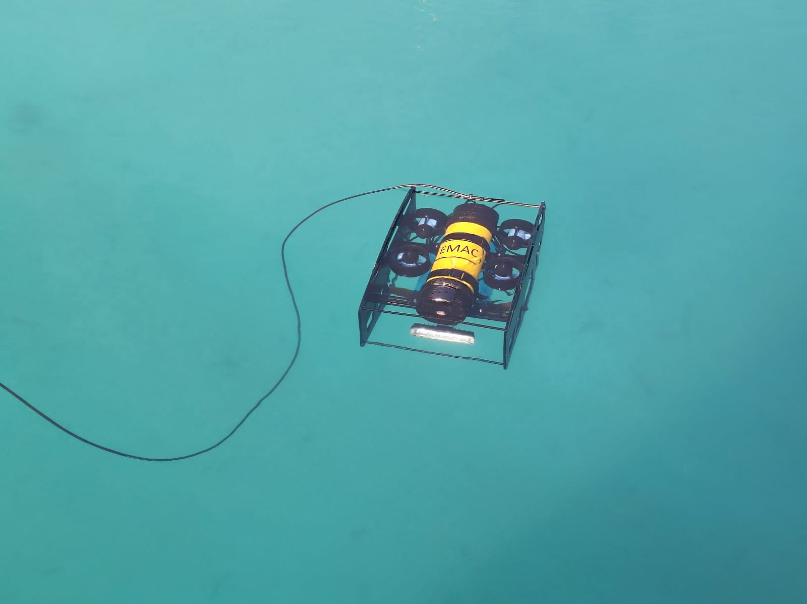
Build and working ROV running the control system.
pid.py: Discrete PID controller for depth control.esc.py: ESC motor controller for thruster speed/direction.adc.py: MCP3208 analog signal reading.filters.py: Signal filtering for motor control.mpu6050.py: MPU6050 accelerometer/gyroscope handler.Update System
sudo apt update && sudo apt upgradeInstall Python and Flask
 sudo apt install python3-full -y
 sudo apt-get install python3-flask
Install MJPG-Streamer: A utility that allows streaming video from a USB camera via HTTP, used for real-time visualization of the ROV's surroundings.
sudo apt install build-essential libjpeg-dev imagemagick libv4l-dev git cmake uvcdynctrl -y cd ~
git clone [https://github.com/jacksonliam/mjpg-streamer.git](https://github.com/jacksonliam/mjpg-streamer.git)
cd mjpg-streamer/mjpg-streamer-experimental
make
sudo make install
Enable Interfaces
sudo raspi-config And navigate to: Interfacing Options → Enable I2C → Enable SPI.
Configure pigpiod Service: pigpiod is a utility that runs the pigpio library as a background process. This allows precise control of the Raspberry Pi's GPIO pins, necessary for sending PWM signals to the motors or ESCs. Enabling it as a service allows it to start automatically with the system and be ready before running the backend.
    sudo apt install pigpio
    sudo systemctl enable pigpiod
    sudo systemctl start pigpiod
Configure Automatic Startup
sudo nano /etc/rc.localAdd the following (adjust paths as needed):
#!/bin/sh -e

sleep 5

cd /home/tobias/mjpg-streamer/mjpg-streamer-experimental
./mjpg_streamer -i "./input_uvc.so -r 640x480 -f 30" -o "./output_http.so -w ./www" &

sleep 10
cd /home/tobias/ControlROV_01/
python /home/tobias/ControlROV/app.py &

exit 0
This automatically launches the video server and the Flask backend at system startup. The sleep command ensures that the camera and network are ready before starting the processes. It is important to note that the paths used (/home/tobias/...) must be adapted to the file structure of the system where the project is implemented.
Verify Services at Startup: This allows checking that the rc.local file executes correctly at startup, including the camera and Flask server.
systemctl status rc-local.serviceIP Address Assignment Configure your router's DHCP settings to assign a static IP to the Raspberry Pi based on its MAC address (e.g., 192.168.0.160).
After this setup is done, the website will load on power on so we can directly access it via the browser of a device in the same network, in the IP address of the RaspberryPi, in the port 5000.
| Function | GPIO Pin | Physical Pin | Connected To |
|---|---|---|---|
| CS (Chip Select) | GPIO 8 | Pin 24 | ADC MCP3208 |
| CLK (Clock) | GPIO 11 | Pin 23 | ADC MCP3208 |
| DOUT | GPIO 9 | Pin 21 | ADC MCP3208 |
| DIN | GPIO 10 | Pin 19 | ADC MCP3208 |
| Digital Output 1 | GPIO 5 | Pin 29 | Digital Output |
| Digital Output 2 | GPIO 6 | Pin 31 | Digital Output |
| Digital Output 3 | GPIO 16 | Pin 36 | Digital Output |
| Digital Output 4 | GPIO 26 | Pin 37 | Digital Output |
| PWM Channel 0 (A) | GPIO 12 | Pin 32 | PWM MDI for ECU |
| PWM Channel 1 (A) | GPIO 13 | Pin 33 | PWM MS for ECU |
| PWM Channel 1 (B) | GPIO 19 | Pin 35 | PWM MDD for ECU |
| PWM Channel 0 (B) | GPIO 18 | Pin 12 | Auxiliary PWM (Camera) |
| SDA | GPIO 2 | Pin 3 | MPU-6050 Accelerometer |
| SCL | GPIO 3 | Pin 5 | MPU-6050 Accelerometer |
To provide a "plug-and-play" experience without a diagnostic screen, GPIO 16 (connected to a relay and high-intensity light) is activated as soon as the backend begins its boot sequence. Once the Flask server is fully initialized and the network is ready for connections, the light turns off automatically, signaling that the ROV is ready for operation.
Maintaining consistent wiring ensures predictable motor rotation direction:
Motor Phase to ESC Connection:
| ESC Color | Motor Color |
|---|---|
| Yellow | Blue |
| Black | Green |
| Red | White |
    ControlROV/
    ├── app.py                 # Main Flask application
    ├── pid.py                 # PID controller implementation
    ├── esc.py                 # ESC motor controller
    ├── adc.py                 # MCP3208 ADC interface
    ├── filters.py             # Signal filtering utilities
    ├── mpu6050.py             # IMU interface
    ├── static/                # Web static files
    │   ├── style.css/
        ├── scripts.js/
    ├── templates/
    │   └── index.html          # HTML
    ├── PCB/                    # PCB diagrams and schematics
    │   └── Modelos3D           # 3D Modeles
    │   └── PCB.kicad_pcb
    │   └── PCB.kicad_pro
│ └── PCB.kicad_schThis section details the software design of the ROV control system, focusing on the interaction between the Backend (hardware logic/control) and the Frontend (web-based user interface).
Although the Flask server and hardware control run on the same Raspberry Pi 4B, the system is conceptually divided into three layers to ensure clear separation of responsibilities:
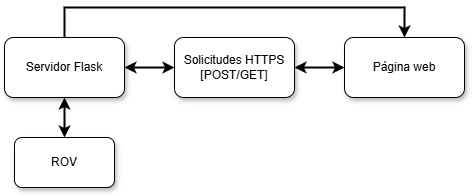
High-Level Architecture.
The backend acts as the brain of the ROV. It manages sensor data acquisition, real-time video streaming, and the PID control loop for depth stabilization.
MJPG-Streamer for low-latency video over IP.
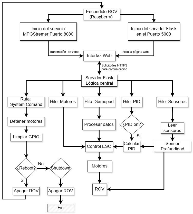
Backend flow diagram.
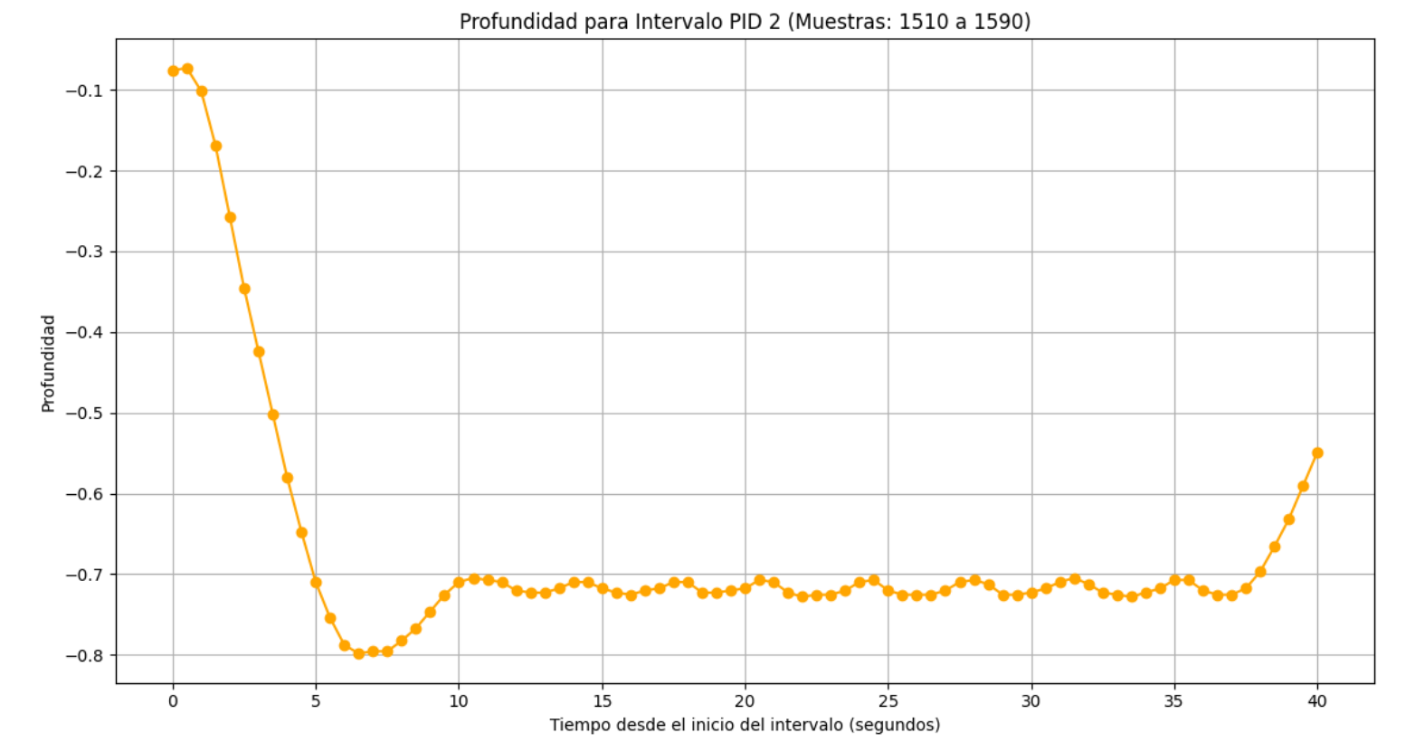
Real-time visualization of the PID controller maintaining depth stability.
The following endpoints allow the Frontend to interact with the ROV's logic:
| Route | Method | Description |
|---|---|---|
/ | GET | Serves the main user interface (index.html). |
/gamepad_data | POST | Receives axes and button data from the controller. |
/update_pid | POST | Updates $K_p$, $K_i$, and $K_d$ coefficients in real-time. |
/read_all | GET | Returns all 8 ADC channel values in JSON format. |
/toggle | POST | Switches the state of a specific GPIO output (e.g., lights). |
/toggle_pid | POST | Enables or disables the depth stabilization loop. |
/get_all_data | GET | Fetches telemetry (pitch, roll, depth, motor states). |
/system_command | POST | Executes OS-level commands like Reboot or Shutdown. |
The frontend is built using HTML, CSS, and vanilla JavaScript. It uses asynchronous HTTP requests to update telemetry and send commands without refreshing the page.
| General Function | Specific Feature | JS Action | Backend Request |
|---|---|---|---|
| PID Tuning | Update coefficients | Form Submission | POST /update_pid |
| Telemetry | Update readings | setInterval() | GET /get_all_data |
| Manual Control | Gamepad input | updateGamepadStatus() | POST /gamepad_data |
| GPIO Toggle | Auxiliary triggers | togglePin(pin) | POST /toggle |
| Datalogger | Recording data | start-btn click | Client-side logic |
| System | Power off / resset | system_comand() | POST /system_command |
| Qty | Value | Footprint | References |
|---|---|---|---|
| 7 | Conn_01x03_Pin | TerminalBlock_Phoenix:TerminalBlock_Phoenix_MKDS-1,5-3-5.08_1x03_P5.08mm_Horizontal | J2, J4, J5, J6, J13, J14, J16 |
| 4 | D | Diode_THT:D_A-405_P10.16mm_Horizontal | D1, D4, D5, D6 |
| 4 | NPN | Package_TO_SOT_THT:TO-92L_HandSolder | Q1, Q2, Q3, Q4 |
| 4 | R | Resistor_THT:R_Axial_DIN0207_L6.3mm_D2.5mm_P7.62mm_Horizontal | R1, R2, R3, R4 |
| 4 | SANYOU_SRD_Form_C | Relay_THT:Relay_SPDT_SANYOU_SRD_Series_Form_C | K1, K4, K5, K6 |
| 1 | 1 | TerminalBlock_Phoenix:TerminalBlock_Phoenix_MKDS-1,5-2-5.08_1x02_P5.08mm_Horizontal | V1 |
| 1 | C_Polarized | Capacitor_THT:CP_Radial_D8.0mm_P5.00mm | C1 |
| 1 | Conn_01x02_Pin | TerminalBlock_Phoenix:TerminalBlock_Phoenix_MKDS-1,5-2-5.08_1x02_P5.08mm_Horizontal | J3 |
| 1 | Conn_01x04_Pin | TerminalBlock_Phoenix:TerminalBlock_Phoenix_MKDS-1,5-4-5.08_1x04_P5.08mm_Horizontal | J7 |
| 1 | Conn_01x07_Pin | TerminalBlock_Phoenix:TerminalBlock_Phoenix_MKDS-1,5-7-5.08_1x07_P5.08mm_Horizontal | J15 |
| 1 | Conn_02x20_Odd_Even | PCB:MODULE_RASPBERRY_PI_4B_4GB | J1 |
| 1 | Fuse | PCB:Fuse_20x5 | F1 |
| 1 | GY-521 | PCB:GY-521 | ACC1 |
| 1 | L7805 | PCB:TO255P1020X450X2000-3 | U3 |
| 1 | MCP3208 | Package_DIP:DIP-16_W7.62mm_Socket | U1 |
| 1 | MPXA6115A | Sensor_Pressure:CFSensor_XGZP6897x | U4 |
| 1 | TRI1-2413 | PCB:XL4005_DC-DC | U2 |

JulienDevillers/vacuumSensorPCB
PCB for vacuum sensor for DIY pick and place machines

IsuriWeerarathne/Smart-BioGas-System
This Project is about a microcontroller-based hardware project on automated biogas system which done as a group project.

ctag-fh-kiel/esp32-eurorack-audio
Open source eurorack audio module based on ESP32

sinneb/esp32-hvcc
Heavy compiler (hvcc) sources running on ESP32-DevKitC powered eurorack module


fpga-theremin/theremin
Open source digital FPGA based theremin project

It measures 191.9 × 68.4 mm and has 2 copper layers, 1.6 mm thick.
35 parts, built around the TRI 1-2413, MCP3208-BI/P, L7805 and MPXA6115A6U. The full list of its parts is on this page, with links to each part's symbol and footprint where PCBKit's library has them.
From the tdominguezmasciale/Control_ROV repository on GitHub, at the commit this page was made from: the board is PCB/PCB.kicad_pcb and its schematic PCB/PCB.kicad_sch. PCBKit opens the board in the browser, with nothing to install.
Its repository publishes it under the GPL-3.0 licence: you may reuse it on that licence's terms (keep the author's notice, and for a copyleft licence share your changes alike).