2 layers14 × 100 mm
Powerline USB C
Andreas-Dorfner/Powerline-USB-C
Powerline is a small 3HP Front Entry USB-C eurorack power supply.
22 parts16

 tauhidansari07/Smart-usb-c-pd-trigger
A compact, low-cost USB-C Power Delivery decoy and utility bench tool. This project allows you to cycle through standard USB-PD profiles (5V, 9V, 12V, 15V, and 20V) at the push of a single button using a standard USB-C…
USB C PD trigger is an open-source printed circuit board by tauhidansari07, from the tauhidansari07/Smart-usb-c-pd-trigger repository on GitHub. It is a 2-layer board of 50.7 × 29 mm with 25 parts on 32 nets, routed with 187 tracks and 59 vias.
It is built around the CH224K and HT7533-1. Its parts include 7 resistors, 5 diodes, 3 capacitors, 3 ICs and 1 connector. It belongs with the power boards and the RISC-V boards of this library.


A compact, low-cost USB-C Power Delivery decoy and utility bench tool. This project allows you to cycle through standard USB-PD profiles (5V, 9V, 12V, 15V, and 20V) at the push of a single button using a standard USB-C wall adapter or power bank.
Unlike basic decoy boards, this design features an active closed-loop feedback mechanism to monitor the actual voltage output, ensuring the status indicators always display accurate readings even if a charger has limited power profiles.
PD4)/firmware : C source code matching standard peripheral libraries (MounRiver Studio / PlatformIO).
/hardware : KiCad schematic and PCB layout design files.
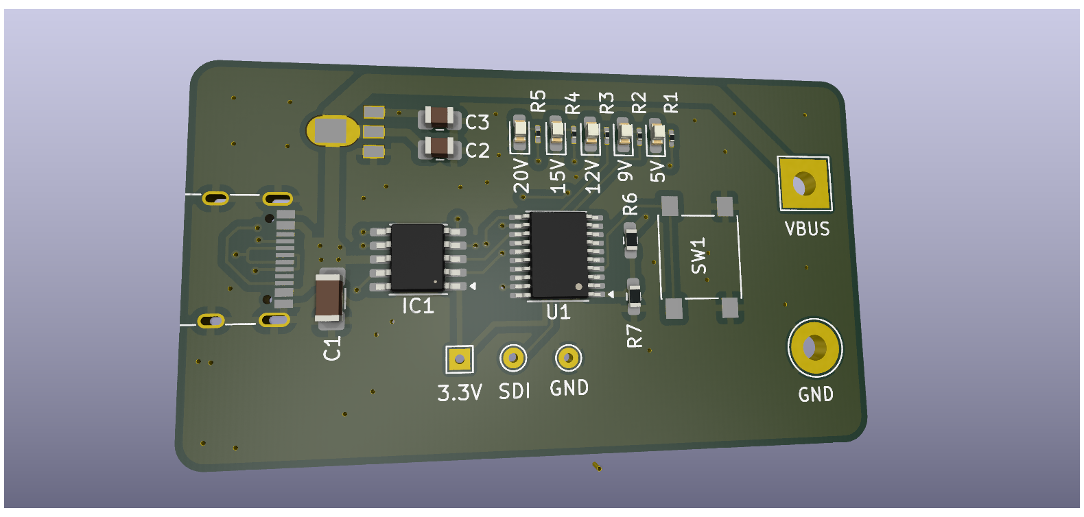
| Qty | Value | Footprint | References |
|---|---|---|---|
| 5 | 1K | Resistor_SMD:R_0201_0603Metric_Pad0.64x0.40mm_HandSolder | R1, R2, R3, R4, R5 |
| 1 | 100K | Resistor_SMD:R_0603_1608Metric_Pad0.98x0.95mm_HandSolder | R6 |
| 1 | 10u | Capacitor_SMD:C_0805_2012Metric_Pad1.18x1.45mm_HandSolder | C3 |
| 1 | 10u | Capacitor_SMD:C_1206_3216Metric_Pad1.33x1.80mm_HandSolder | C1 |
| 1 | 12V | LED_SMD:LED_0603_1608Metric_Pad1.05x0.95mm_HandSolder | D3 |
| 1 | 15K | Resistor_SMD:R_0603_1608Metric_Pad0.98x0.95mm_HandSolder | R7 |
| 1 | 15V | LED_SMD:LED_0603_1608Metric_Pad1.05x0.95mm_HandSolder | D4 |
| 1 | 1u | Capacitor_SMD:C_0805_2012Metric_Pad1.18x1.45mm_HandSolder | C2 |
| 1 | 20V | LED_SMD:LED_0603_1608Metric_Pad1.05x0.95mm_HandSolder | D5 |
| 1 | 3.3V | TestPoint:TestPoint_THTPad_1.5x1.5mm_Drill0.7mm | TP1 |
| 1 | 5V | LED_SMD:LED_0603_1608Metric_Pad1.05x0.95mm_HandSolder | D1 |
| 1 | 9V | LED_SMD:LED_0603_1608Metric_Pad1.05x0.95mm_HandSolder | D2 |
| 1 | CH224K | Package_SO:SSOP-10-1EP_3.9x4.9mm_P1mm_EP2.1x3.3mm | IC1 |
| 1 | CH32V003FxPx | Package_SO:TSSOP-20_4.4x6.5mm_P0.65mm | U1 |
| 1 | GND | TestPoint:TestPoint_THTPad_D4.0mm_Drill2.0mm | TP5 |
| 1 | GND | TestPoint:TestPoint_THTPad_D1.5mm_Drill0.7mm | TP2 |
| 1 | HT7533-1 | sot89 lib:SOT89 | U2 |
| 1 | SDI | TestPoint:TestPoint_THTPad_D1.5mm_Drill0.7mm | TP3 |
| 1 | SW_Push | sot89 lib:SW_Push_1P1T_NO_6x6mm_H9.5mm | SW1 |
| 1 | USB_C_Receptacle_USB2.0_16P | Connector_USB:USB_C_Receptacle_G-Switch_GT-USB-7010ASV | J1 |
| 1 | VBUS | TestPoint:TestPoint_THTPad_4.0x4.0mm_Drill2.0mm | TP4 |
Andreas-Dorfner/Powerline-USB-C
Powerline is a small 3HP Front Entry USB-C eurorack power supply.


hackclub/OnBoard
💡 Join 1,000 teenagers and make your first PCB with a $100 grant!

jackw01/scanlight
A better light source for scanning color negative film


CrashOverride85/zc95
4 channel EStim box inspired by the mk312bt, with Lua scripting support


GrappleRobotics/JMS
Another alternative field management system for the FIRST Robotics Competition.
It measures 50.7 × 29 mm and has 2 copper layers, 1.6 mm thick.
25 parts, built around the CH224K and HT7533-1. The full list of its parts is on this page, with links to each part's symbol and footprint where PCBKit's library has them.
From the tauhidansari07/Smart-usb-c-pd-trigger repository on GitHub, at the commit this page was made from: the board is USB C PD trigger.kicad_pcb and its schematic USB C PD trigger.kicad_sch. PCBKit opens the board in the browser, with nothing to install.
Its repository states no licence, so its author keeps all rights: ask tauhidansari07 before reusing the design.