2 layers105 × 71.5 mm
Pcbcar
Taran-the-Idiot/taranium-rover
This thing is really big so you need like a lot of plates if you want to build it. Roughly about 6 plates and 40 hours of non stop printing.
26 parts5

 Taran-the-Idiot/taranium-rover5
This thing is really big so you need like a lot of plates if you want to build it. Roughly about 6 plates and 40 hours of non stop printing.
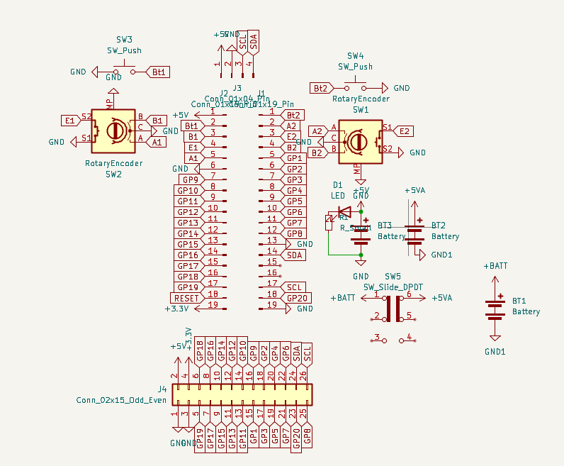
Controller is an open-source printed circuit board by Taran-the-Idiot, from the Taran-the-Idiot/taranium-rover repository on GitHub. It is a 2-layer board of 79.8 × 60.6 mm with 18 parts on 44 nets, routed with 141 tracks and 0 vias.
Its parts include 5 switches, 4 connectors, 1 resistor and 1 diode.
Made By Overlord Runt // Taran The Idiot
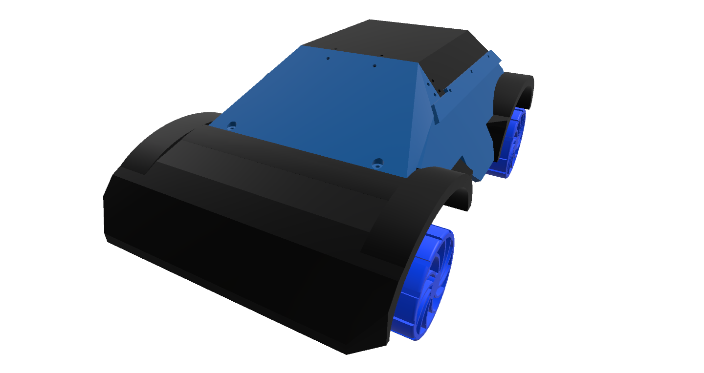
This is an RC car I made for Hack Club's Highway. It has a 4WD system and can turn with all 4 wheels. It uses ESP32 and ESPNow to communicate between the car and the controller
Majority of this project was getting the cadding of all the different parts done. This isnt what normal custom RC Cars look like and thats because everyone uses the exact same optimal design but I want to make and design something myself. idrc about the "optimal way" cuz where is the fun in that.
This thing is really big so you need like a lot of plates if you want to build it. Roughly about 6 plates and 40 hours of non stop printing.
It uses a crap ton of M3 screws and heatsets, so make sure you stock up on those
So bunch of enginnering went into this design. First the turning system. the 2 front wheels turn separately to allow for differential steering and reduced drag. It also allows me to use weaker and smaller 9g servos that are able to turn one wheel, but not 2.
It used steel dowels to hold the pieces together and to ensure minimal friction between parts(make it turn stronger)
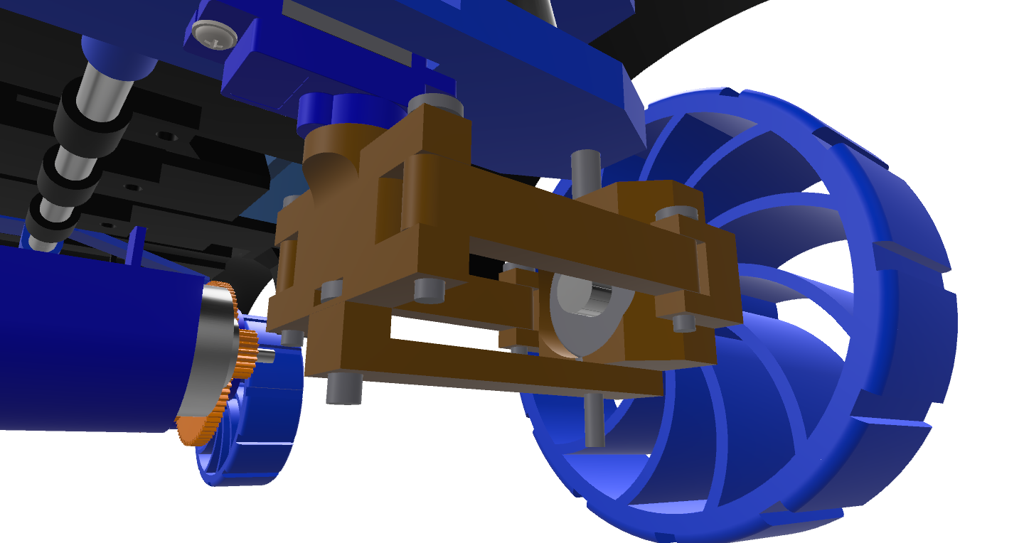
The bottom piece is there for stability and to make sure the wheel mount doesnt collapse.
The suspensions are a bunch of high strendth springs that help distribute the weight of the whole car evenly through the wheels and absorb large bumps.
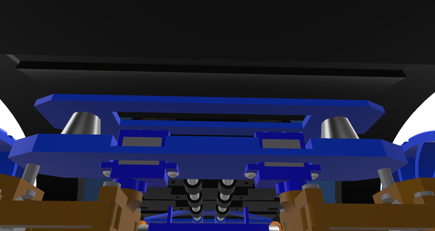
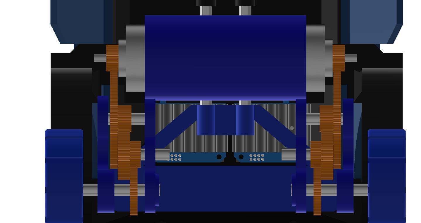
The gear system uses a 16:1 gear down from the 12 000 rpm motor to give a 750 rpm spin under no load with roughly 6-10 Kgcm torque. under load it will have about 4-500 rpm and go about 1m/s. I use a large amount of bearings and steel rods in this design. For assembly, use a grinder to chop the steel rods into all the different lengths needed. You can refer to Full-Build.step in the CAD folder to see how everything is put together.
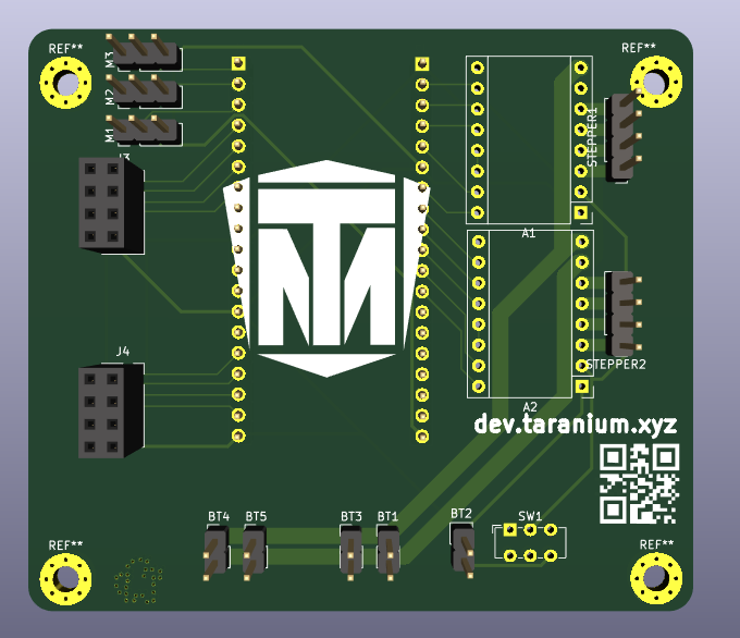
The PCB didnt really take too long but I did have to make many different revisions to get here that did end up taking a lot of time.
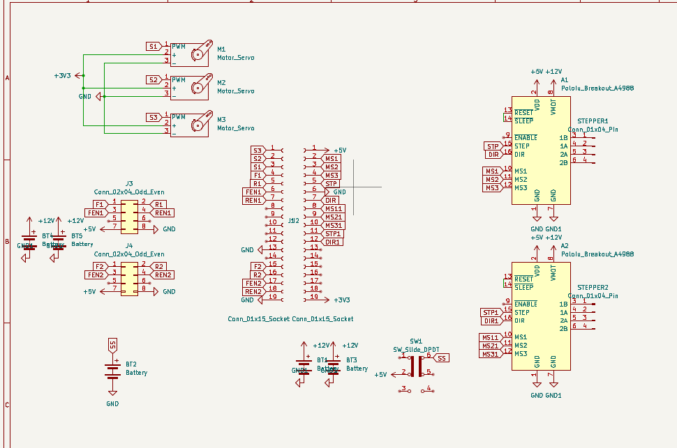
I wanted this to be somewhat of a universal mainboard that could be used in multiple use cases. Which is why I included space for stepper motor drivers. specifically the A4988. as well as 3 places for servos
The PCB features 2 BTS7960 motor drivers. They have 8 pins that connect to the boards(mounted externally). The mainboard also has space to use A4988 stepper motor drivers if you wish to swap out the 775s for stepper motors.
I didnt have a footprint for the esp32 board that I am using so I just used 2 header pins and separated them the distance that it said on the datasheet.
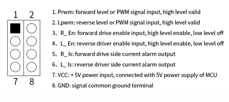
this is the pinout for the Motor driver. it mathces that on the pcb so its an easy connection there
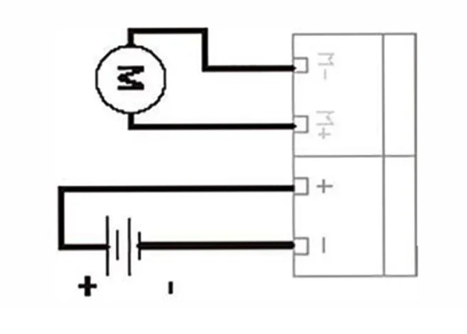
This is how you connect the motor driver to the battery and to the motor.
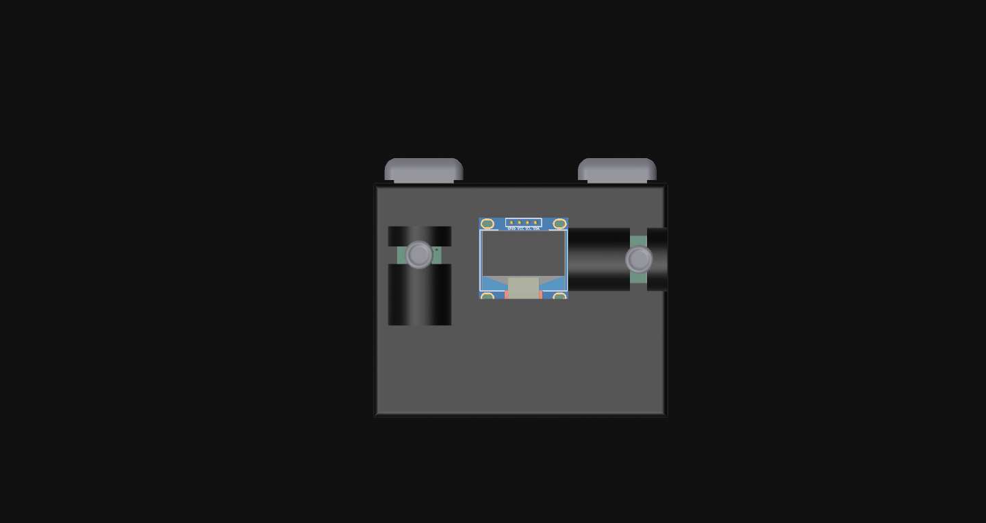
The controller was fairly easy to cad. it uses M3 screws to hold itself together.
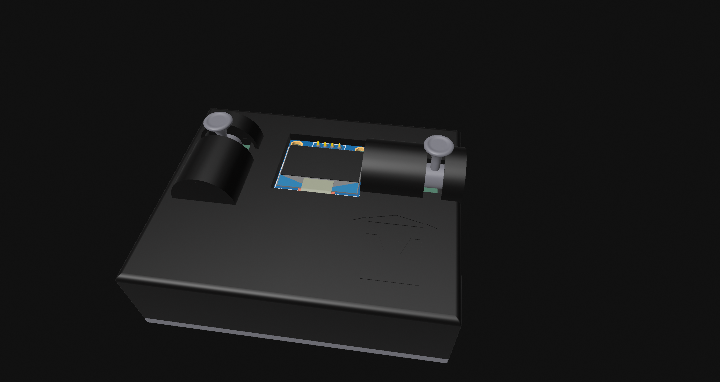
The triggers are just extensions to the buttons with a small indent to act as a stabiliser
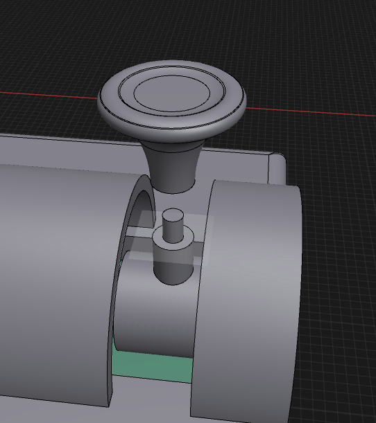
The joysticks/encoder rods are cool in that I didn't use the revolve tool to make them. just a bunch of extrusions, drafts, and fillets.
Then in order to make it actually buildable, i chopped off the end and added a dowel
For the pcb I wanted to keep it basic. So 2 encoders. One for speed, other for turning. then 2 buttons. one to reverse, other for anything else you might wanna add in the future.
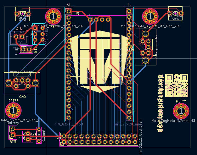
Its a cool design if you ask me and it does its job.
uses espnow and you can find the firmware in the firmware folders. the names should tell you all you need to knwo about which on goes to which but for those who are a little slow, controller.ino flashes to the controller and mainboard.ino flashes to the mainboard
If i forgot something I will add it on when I build
| Name | QTY | Cost(AUD) | Cost(USD) | Link |
|---|---|---|---|---|
| 3s 2.2AH LiPo | 1 | $47.19 | LINK | |
| ESP32 Dev Board | 2 | $7.39 | LINK | |
| Buck Converter | 1 | $1.47 | LINK | |
| Steel Rods | 1 | $13.59 | LINK | |
| 775 12V DC Motor | 2 | $31.40 | 20.2 | LINK |
| BTS7960 Motor Driver | 2 | $15.00 | 9.65 | LINK |
| Header Pins | 1 | $2.54 | LINK | |
| Servo Motor 5V | 2 | $4.69 | LINK | |
| M3x10mm Screws | $2.82 | LINK | ||
| M3x16mm Screws | $3.43 | LINK | ||
| M3x6mm Screws | $2.29 | LINK | ||
| M3D5L6 Heatsets | 45 | $3.82 | LINK | |
| M3 Steel Dowels 20mm | 4 | $2.47 | LINK | |
| M3 Steel Dowels 12mm | 2 | $2.41 | LINK | |
| M4 Steel Dowels 12mm | 2 | $2.47 | LINK | |
| M5 Steel Dowels 25mm | 2 | $3.16 | LINK | |
| Car Mainboard | 1 | 9.18 | $6.90 | JLCPCB |
| Controller Board | 1 | 15.1 | $9.87 | JLCPCB |
| 3d Printed parts | I aint counting how many there are | |||
| LiPo Balance Charger | 1 | $23.95 | LINK | |
| Horizontal Rotary Encoder | 2 | $4.90 | LINK | |
| T-plug connector | 1 | $2.61 | LINK | |
| 10 gauge wire | 2m | $15.45 | LINK | |
| 3.7V lipo | 1 | $14.99 | LINK | |
| XH 2.54 Male connector | 1 | $1.79 | LINK | |
| 6mm switch | 2 | $2.89 | LINK | |
| Hardened Springs | 4 | sourced from my dad | ||
| 1kg PLA | 1 | |||
| 1kg PETG | 1 | |||
| Boost Converter | 1 | $4.83 | LINK | |
| SSD1306 128x64 OLED Display | 1 | $4.20 | LINK | |
| TOTAL | $246.03 | $161.03 |
| Qty | Value | Footprint | References |
|---|---|---|---|
| 2 | Battery | Connector_PinSocket_2.54mm:PinSocket_1x02_P2.54mm_Vertical | BT2, BT3 |
| 2 | Conn_01x19_Pin | Connector_PinSocket_2.54mm:PinSocket_1x19_P2.54mm_Vertical | J1, J2 |
| 2 | RotaryEncoder | Taranium-libs:EC11-Horizontal | SW1, SW2 |
| 2 | SW_Push | Taranium-libs:Button-6mm-2pin-tht | SW3, SW4 |
| 1 | Battery | Connector_JST:JST_XH_B2B-XH-A_1x02_P2.50mm_Vertical | BT1 |
| 1 | Conn_01x04_Pin | Taranium-libs:MODULE_DM-OLED096-636 | J3 |
| 1 | Conn_02x15_Odd_Even | Connector_PinHeader_2.54mm:PinHeader_2x13_P2.54mm_Vertical | J4 |
| 1 | LED | LED_THT:LED_D3.0mm | D1 |
| 1 | R_Small | Resistor_THT:R_Axial_DIN0204_L3.6mm_D1.6mm_P5.08mm_Horizontal | R1 |
| 1 | SW_Slide_DPDT | Button_Switch_THT:SW_E-Switch_EG1271_SPDT | SW5 |
The 14 most common of 18 parts.
Taran-the-Idiot/taranium-rover
This thing is really big so you need like a lot of plates if you want to build it. Roughly about 6 plates and 40 hours of non stop printing.


VoronDesign/Voron-Hardware
Cool Hardware designed by the Voron Design group


hackclub/OnBoard
💡 Join 1,000 teenagers and make your first PCB with a $100 grant!

VoronDesign/Voron-Tap
Tap is a nozzle-based z-probe for the V2 and Trident printer designs. The entire toolhead moves to trigger an optical switch. Tap offers many advantages:

Luos-io/luos_engine
Open-source and real-time orchestrator for cyber-physical-systems, to easily design, test and deploy embedded applications and digital twins.


Twotoz/C5VRX
Ultra-minimal, zero-CPU 5.8 GHz analog FPV video receiver using ESP32-C5 Wi-Fi 6 PHY MODEM_DIAG, BitScrambler WBFM demodulation & resistor DAC CVBS
It measures 79.8 × 60.6 mm and has 2 copper layers, 1.6 mm thick.
18 parts. The full list of its parts is on this page, with links to each part's symbol and footprint where PCBKit's library has them.
From the Taran-the-Idiot/taranium-rover repository on GitHub, at the commit this page was made from: the board is Controller/Controller.kicad_pcb and its schematic Controller/Controller.kicad_sch. PCBKit opens the board in the browser, with nothing to install.
Its repository states no licence, so its author keeps all rights: ask Taran-the-Idiot before reusing the design.