Skip to the content
2 layers214 × 111 mmMesa2, the printed circuit board in 3D

Design files for my keyboards

Size
214 × 111 mm
Copper layers
2
Thickness
1.6 mm
Parts
55
Nets
43
Pads
247
Tracks, vias
409, 41
Routed
Yes
KiCad
KiCad 10.0 (file 20260206)
Created
30 Oct 2022
Updated
27 Sep 2026

Overview

Mesa2 is an open-source printed circuit board by tangybbq, from the tangybbq/keyboard repository on GitHub. It is a 2-layer board of 214 × 111 mm with 55 parts on 43 nets, routed with 409 tracks and 41 vias.

It is built around the 1N4148W and SK6812MINI-HS. Its parts include 4 capacitors, 4 diodes and 1 connector. It belongs with the keyboards and input boards of this library.

Main components

2

README

README.md

David Brown (d3zd3z) keyboard designs

This repo captures the design files associated with my custom keyboards.

These keyboards are primarily focused on Steno input, mainly using Plover. In the spirit of open steno, I have made these designs open. Anyone is free to make designs based on these keyboards, for non-commercial purposes. I am releasing the designs under the CC BY-NC 3.0 license. Specifically, this means if you wish to sell a product based on the design, you should talk to me.

The "Jolt" keyboard

At this point, I've decided to give the keyboard a real name, hence "jolt". The jolt 1 is still in Eagle, and I may migrate the files here.

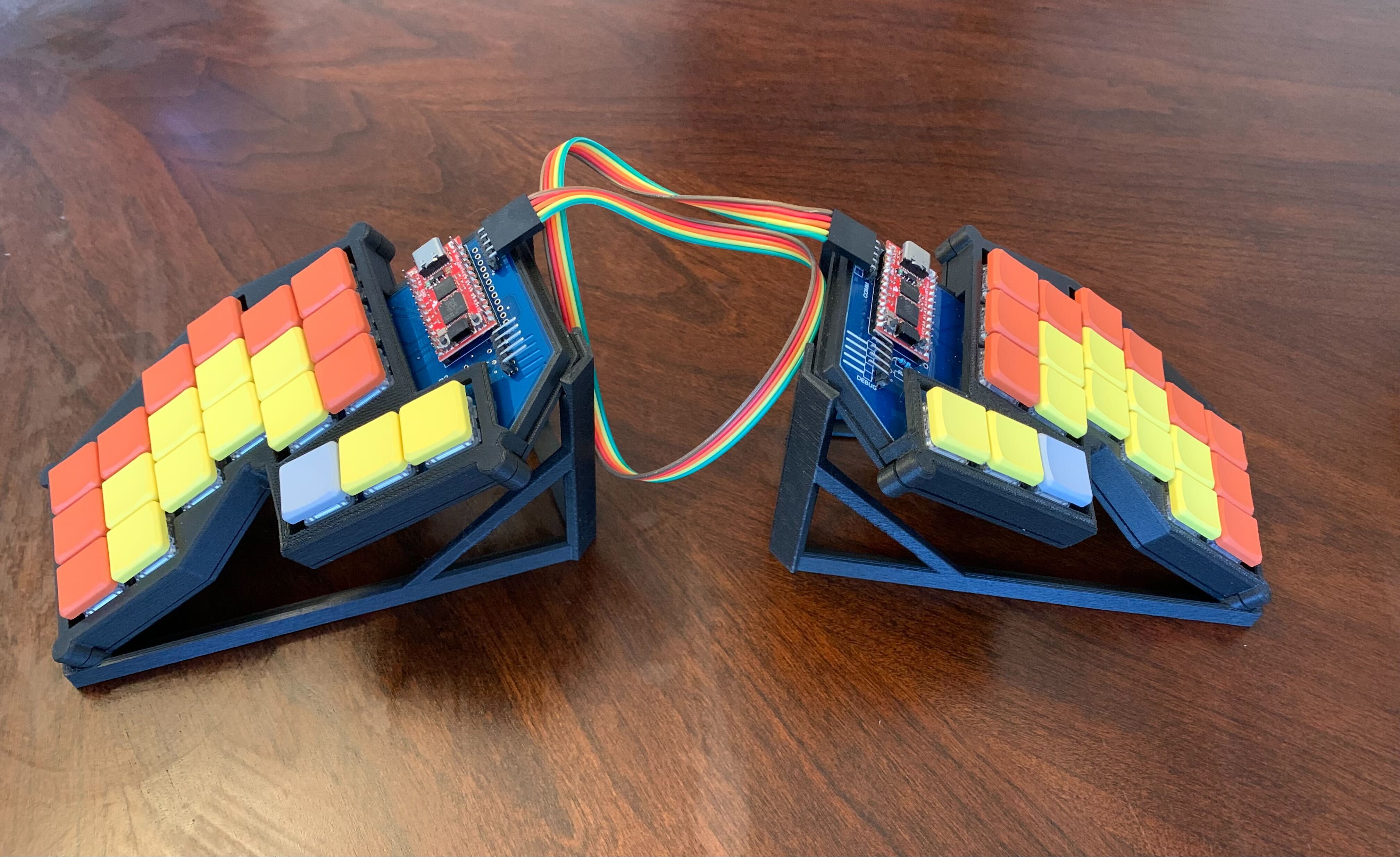
But, I have added the "jolt2". The jolt2 is an experiment beyond just a traditional corne-like keyboard, and something fully in 3-space, like the dactyl. There are individual base plates for left and right, and then small strips of 3 keys for each column. The base PCB has 4 pairs of pin headers to support these individual 3-key columns. This will allow me to experiment with elevation as well as just the X and Y position of each key. I still want each column to be at the same elevation, because I rely heavily on pressing keys together (both for my qwerty layout, and for steno).

At this point, there are 4 PCBs here:

  • jolt2-left: The layout of the left side using a directly assembled rp2040
  • jolt2-tiny2040-left: The same left side pcb, but built around the Pimoroni Tiny 2040. Note that only the left side needs the 8MB version (to hold the steno dictionary), but I just ordered all the same, and use the 8MB version on each side.
  • jolt2-tiny2040-right: The Tiny 2040-based, made for the right side.
  • jolt2-verts: These are the small 3-key support boards. It will take 28 of these, plus a left and a right to build a full keyboard.

In addition, there is also a jolt2-pim-left, based around the Pimoroni PGA2350. There are numerous errors in this that need to be fixed, as I messed up the reference numbers for the headers to the key-boards.

The "bletest2"

This isn't really a keyboard, but my experiments putting an nRF5340 module on a board. This is work in progress, and has numerous things I've discovered wrong with it. I will work to improve it over time:

  • The power supply was suppose to auto switch between USB power and battery power. However, I accidentally chose a boost converter instead of a boost/buck converter, and if USB is connected, all it does is fry everything on the board. You can either leave out D1, or install a chain of diodes in its place (I used 5) to drop the voltage enough to make VBUS less than the 3.3. Auto-switching will probably end up preferring the battery, though, so I just recommend removing D1 entirely, and powering the board off of the batteries.
  • The RGB LEDs don't work. I'm not quite sure what is wrong, as I see no signal on the DIN pin. I maybe have issues, given the difficult of properly soldering down the BLE module.
  • The LEDs probably need a 5V supply, which isn't readily available. Realistically, if I build a battery power device, I'll likely just use an analog RGB component, and use 3 gpios with PWM.

The intent was to be able to remove the various jumpers, and use the Power Profiler Kit II to observer power consumption. Despite rev 2, I'm still not far enough along with this to be able to do that meaningfully.

The "shield-kb1"

This is an Arduino-style shield, designed to plug into the nRF5340 DK. It provides non-working LEDs, a 2x2 keyboard matrix, and inter-board headers for left and right that should allow it to talk to the jolt or proto3 designs.

The "proto3"

This is basically the same design as the proto2, but with a third row. The qmk supports an easier qwerty mode, but still with a modified homerow modifier support (I use the lower row as it has slightly fewer rollover conflicts).
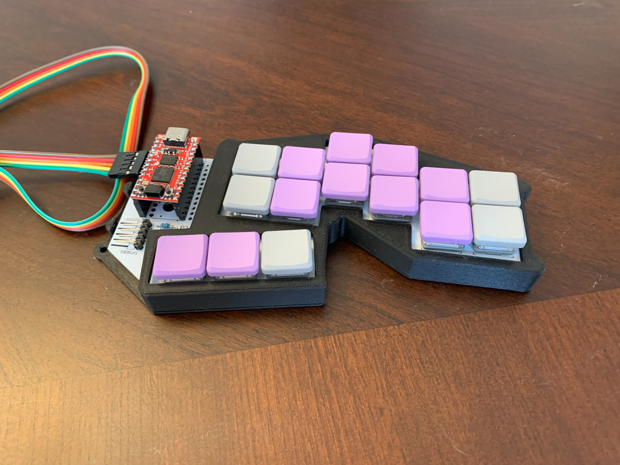
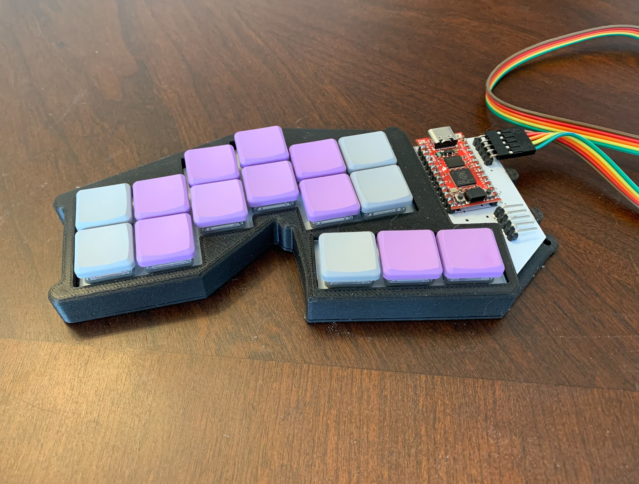
proto3

The BOM is the same as the proto2, but it will need 42 diodes.

The "proto2"

For lack of a better name, this first design is called the "proto2".
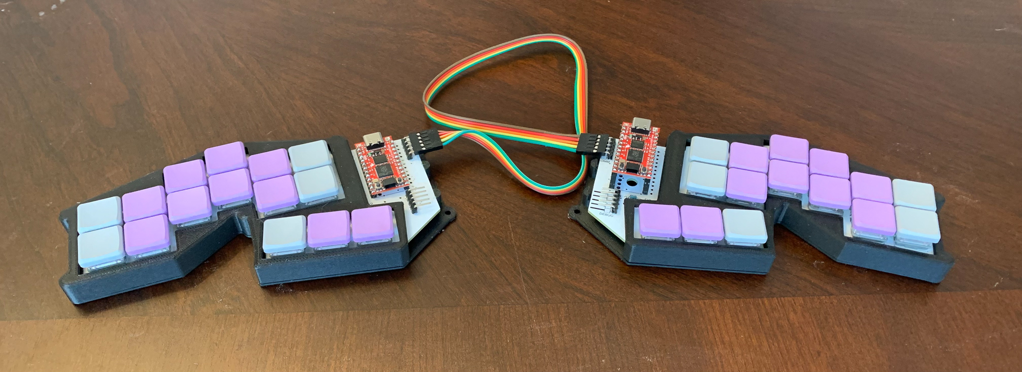
full-proto2

left-proto2

right-proto2

There was an earlier prototype, that was handwired, and rather fragile. This is the first version I would consider to be a usable keyboard. In the above pictures, the left half has the MCU (Pro Micro RP2040) soldered directly to a header, soldered to the PCB, and the right one uses a socket.

To build this, in addition to the PCBs, you will need

  • 2 Pro Micro RP2040 boards. At the time of my build, these are running about $11, and seem readily available.
  • 30 Kailh Choc switches. I sourced mine from Mkultra. I recommend the "pink" version, which has 20gf springs, and I find work well.
  • 30 keycaps for these switches. I used the MBK Factory Colors keycaps, which allows me to make the "primary" keys stand out a little, and just looks rather nice.
  • 30 general purpose SOD123 diodes. I got BAV19W, although almost any diode will work for this.
  • 2 or 4 5-pin right angle headers. Two are needed for the communication between the boards. The others are interested if you want to use SWD, since the RP2040 Pro Micro inconveniently puts these connectors on the underside of the board.

The PCB is reversable. The RP2040 board should be mounted in the labeled holes, which is always the left set when viewed from the top. The diodes are intended to be soldered to the bottom side of the board.

I have also a case design that can be 3d printed. The models are for the right side. Use your slicing software to mirror about the X axis to print the pieces for the other side.

The firmware I am using for this keyboard is in my fork of QMK.

Parts

55
QtyValueFootprintReferences
191N4148WDiode_SMD:D_SOD-123D_LA1, D_LBK1, D_LE1, D_LI1, D_LN1, D_LO1, D_LS1, D_LSP1, D_LT1, D_RA1, D_RBK1, D_RE1, D_RI1, D_RN1, D_RO1, D1 +3
18SW_PG1350mesa1:Kailh_socket_PG1350SW_LA1, SW_LBK1, SW_LE1, SW_LI1, SW_LN1, SW_LO1, SW_LS1, SW_LSP1, SW_LT1, SW_RA1, SW_RBK1, SW_RE1, SW_RI1, SW_RN1, SW_RO1, SW_RS1 +2
6MountingHoleMountingHole:MountingHole_2.2mm_M2H1, H2, H3, H4, H5, H6
4100nFCapacitor_SMD:C_0603_1608Metric_Pad1.08x0.95mm_HandSolderC1, C2, C3, C4
4SK6812MINI-HSmesa1:SK6812-MINI-HSLED1, LED2, LED3, LED4
1Pimoroni_Tiny2040mesa1:Pimoroni_Tiny2040A1
1RESET_WIRETestPoint:TestPoint_Pad_2.0x2.0mmRESET1
1SolderJumper_2_OpenJumper:SolderJumper-2_P1.3mm_Open_RoundedPad1.0x1.5mmJP1
1Tag-Connect TC2030Connector:Tag-Connect_TC2030-IDC-FP_2x03_P1.27mm_VerticalJ2

More from tangybbq/keyboard

12
  • 2 layers151 × 98 mmJolt2-left, the printed circuit board in 3D

    Jolt2-left

    tangybbq/keyboard

    Design files for my keyboards

    65 parts21
  • 2 layers78.5 × 52 mmBletest-2, the printed circuit board in 3D

    Bletest-2

    tangybbq/keyboard

    Design files for my keyboards

    45 parts21
  • 2 layers151 × 98 mmJolt2-pim left, the printed circuit board in 3D

    Jolt2-pim left

    tangybbq/keyboard

    Design files for my keyboards

    42 parts21
  • 2 layers133 × 94 mmMesa1-left, the printed circuit board in 3D

    Mesa1-left

    tangybbq/keyboard

    Design files for my keyboards

    38 parts21
  • 2 layers124 × 111 mmMesa3-left, the printed circuit board in 3D

    Mesa3-left

    tangybbq/keyboard

    Design files for my keyboards

    38 parts21
  • 4 layers38 × 38 mmJ3-mez-2040, the printed circuit board in 3D

    J3-mez-2040

    tangybbq/keyboard

    Design files for my keyboards

    37 parts21
  • 2 layers133 × 94 mmProto4-left, the printed circuit board in 3D

    Proto4-left

    tangybbq/keyboard

    Design files for my keyboards

    37 parts21
  • 2 layers134 × 94 mmProto4-duplex, the printed circuit board in 3D

    Proto4-duplex

    tangybbq/keyboard

    Design files for my keyboards

    36 parts21
  • 2 layers151 × 98 mmJolt2-pm2350-left, the printed circuit board in 3D

    Jolt2-pm2350-left

    tangybbq/keyboard

    Design files for my keyboards

    35 parts21
  • 2 layers151 × 98 mmJolt2-tiny2040-left, the printed circuit board in 3D

    Jolt2-tiny2040-left

    tangybbq/keyboard

    Design files for my keyboards

    34 parts21
  • 4 layers151 × 98 mmJolty-2040, the printed circuit board in 3D

    Jolty-2040

    tangybbq/keyboard

    Design files for my keyboards

    34 parts21
  • 2 layers151 × 98 mmJolt3-right, the printed circuit board in 3D

    Jolt3-right

    tangybbq/keyboard

    Design files for my keyboards

    33 parts21

Similar boards

  • 2 layers31.3 × 67 mmRPBoard², the printed circuit board in 3D

    RPBoard²

    euvalennn/rpboard-squared

    Simple RP2350-based devboard

    63 parts9
  • 2 layers55.1 × 26 mmEsp8266, the printed circuit board in 3D

    Esp8266

    besi/esp8266-pcb

    The 16MB flash chip need some special settings when flashing:

    47 parts1
  • 2 layers343.7 × 135.1 mmLzIron RP2040, the printed circuit board in 3D

    LzIron RP2040

    Keyboard-PCB-Replica-Project/lzIron_RP2040

    이 기판은 MX 버전이며, ISO 엔터 및 Alps를 지원하지 않습니다!

    237 parts1
  • 2 layers45.2 × 95 mmMakroboard, the printed circuit board in 3D

    Makroboard

    L-S-2020/leoboard

    A makroboard for video editing with premiere pro.

    16 parts1
  • 4 layers40.3 × 68.8 mmNrfMain, the printed circuit board in 3D

    NrfMain

    batkay/CapstonePCB

    76 parts
  • 2 layers137.5 × 132 mmSmartCubePanel, the printed circuit board in 3D

    SmartCubePanel

    Dennis960/SmartCube

    SmartCube is a smart cube that can magnetically connect to other cubes in four directions

    767 parts
  • 2 layers45 × 95 mmAirquality, the printed circuit board in 3D

    Airquality

    MorgenWebDigital/airquality

    A battery-powered indoor air quality monitor. Real CO₂ from a photoacoustic sensor, VOC and NOx, temperature, humidity and ambient light, shown on a 2.13" e-paper display and sent over Bluetooth LE.

    78 parts
  • 4 layers67 × 83 mmApple peeler pcb, the printed circuit board in 3D

    Apple peeler pcb

    SIGPLAN-AV/apple-peeler

    HDMI MITM device aimed at supplying crafted EDID to make Apple sources behave

    138 parts

Questions

How big is the Mesa2 PCB?

It measures 214 × 111 mm and has 2 copper layers, 1.6 mm thick.

What parts does the Mesa2 use?

55 parts, built around the 1N4148W and SK6812MINI-HS. The full list of its parts is on this page, with links to each part's symbol and footprint where PCBKit's library has them.

Where can I download the Mesa2 KiCad files?

From the tangybbq/keyboard repository on GitHub, at the commit this page was made from: the board is mesa2/mesa2/mesa2.kicad_pcb. PCBKit opens the board in the browser, with nothing to install.

Can I use the Mesa2 design in my own project?

Its repository states no licence, so its author keeps all rights: ask tangybbq before reusing the design.