2 layers214 × 111 mm

 tangybbq/keyboard21
Design files for my keyboards
Jolt2-left is an open-source printed circuit board by tangybbq, from the tangybbq/keyboard repository on GitHub. It is a 2-layer board of 151 × 98 mm with 65 parts on 64 nets, routed with 454 tracks and 58 vias.
It is built around the RP2040, W25Q128JVPIQ and SK6812MINI-HS, with the ABM8-272-T3 and RJ45 among its other parts. Its parts include 31 connectors, 16 capacitors, 10 resistors, 3 ICs and 2 diodes. It belongs with the keyboards and input boards and the RP2040 boards of this library.


This repo captures the design files associated with my custom keyboards.
These keyboards are primarily focused on Steno input, mainly using Plover. In the spirit of open steno, I have made these designs open. Anyone is free to make designs based on these keyboards, for non-commercial purposes. I am releasing the designs under the CC BY-NC 3.0 license. Specifically, this means if you wish to sell a product based on the design, you should talk to me.
At this point, I've decided to give the keyboard a real name, hence "jolt". The jolt 1 is still in Eagle, and I may migrate the files here.
But, I have added the "jolt2". The jolt2 is an experiment beyond just a traditional corne-like keyboard, and something fully in 3-space, like the dactyl. There are individual base plates for left and right, and then small strips of 3 keys for each column. The base PCB has 4 pairs of pin headers to support these individual 3-key columns. This will allow me to experiment with elevation as well as just the X and Y position of each key. I still want each column to be at the same elevation, because I rely heavily on pressing keys together (both for my qwerty layout, and for steno).
At this point, there are 4 PCBs here:
In addition, there is also a jolt2-pim-left, based around the Pimoroni PGA2350. There are numerous errors in this that need to be fixed, as I messed up the reference numbers for the headers to the key-boards.
This isn't really a keyboard, but my experiments putting an nRF5340 module on a board. This is work in progress, and has numerous things I've discovered wrong with it. I will work to improve it over time:
The intent was to be able to remove the various jumpers, and use the Power Profiler Kit II to observer power consumption. Despite rev 2, I'm still not far enough along with this to be able to do that meaningfully.
This is an Arduino-style shield, designed to plug into the nRF5340 DK. It provides non-working LEDs, a 2x2 keyboard matrix, and inter-board headers for left and right that should allow it to talk to the jolt or proto3 designs.
This is basically the same design as the proto2, but with a third row. The qmk supports an easier qwerty mode, but still with a modified homerow modifier support (I use the lower row as it has slightly fewer rollover conflicts).
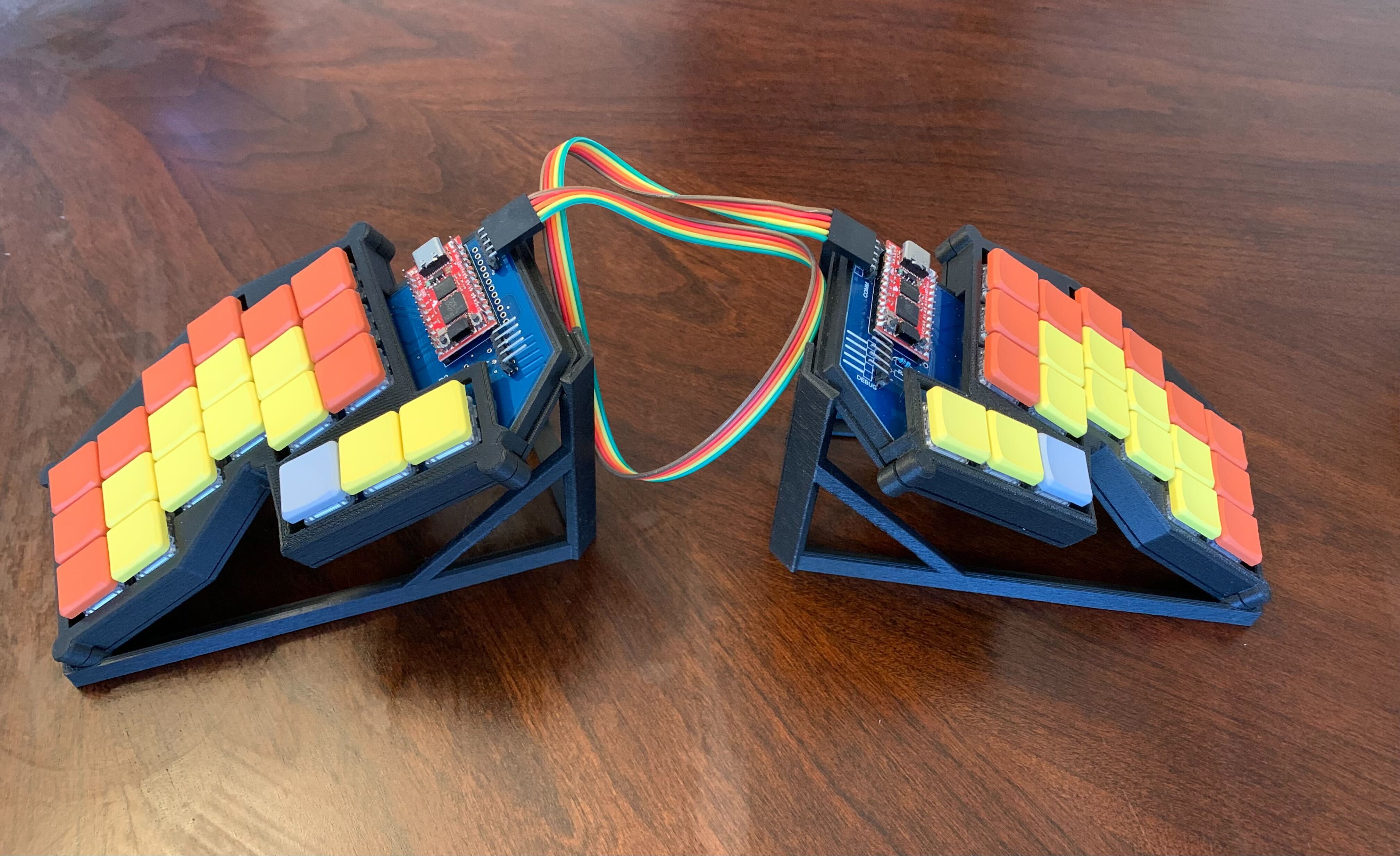
The BOM is the same as the proto2, but it will need 42 diodes.
For lack of a better name, this first design is called the "proto2".
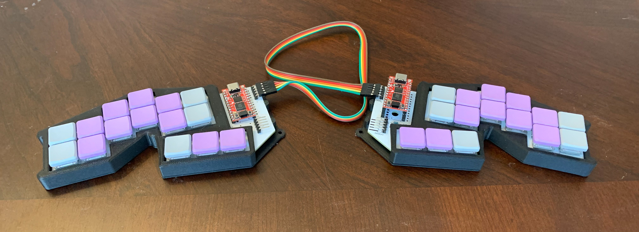
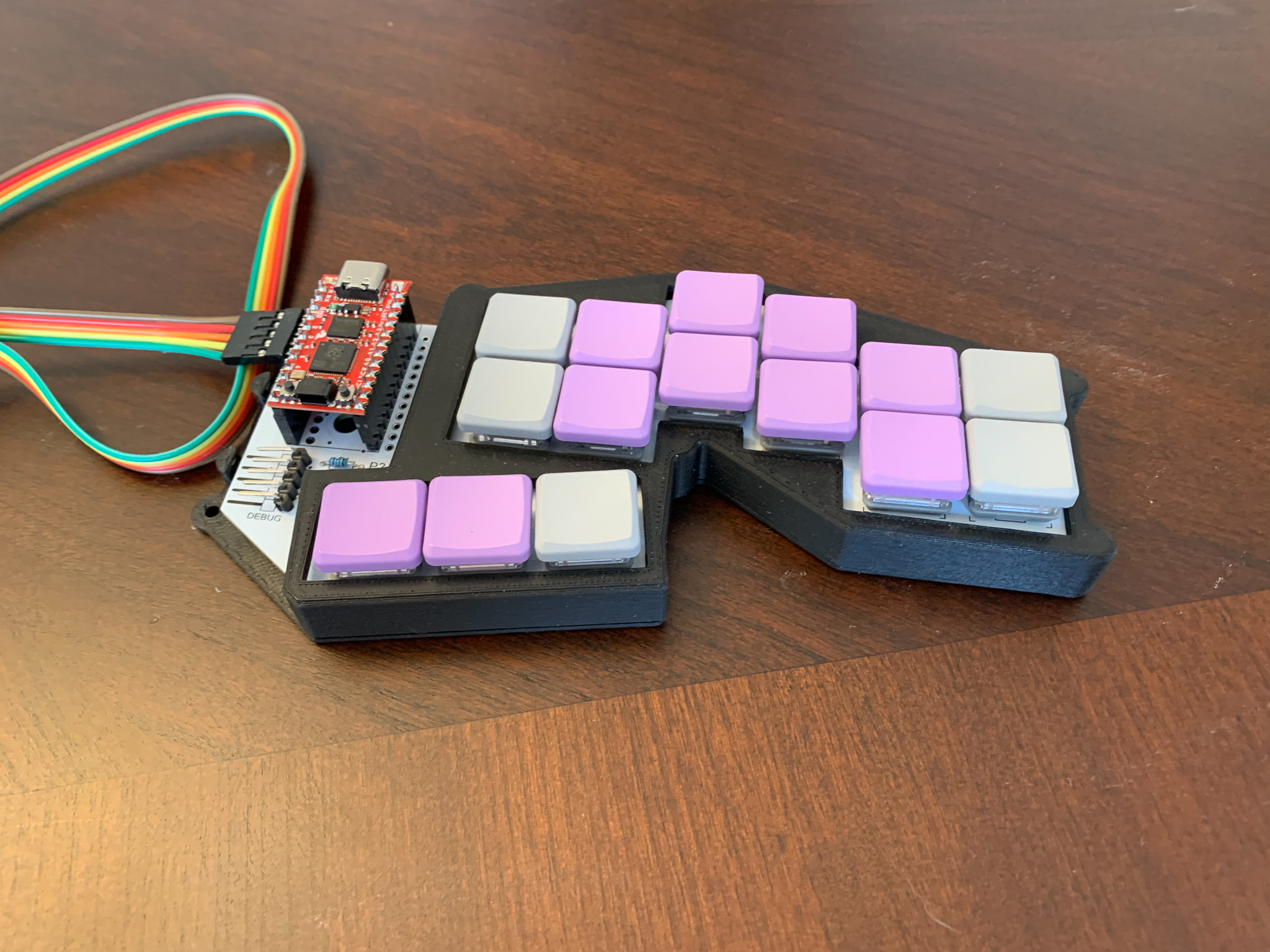
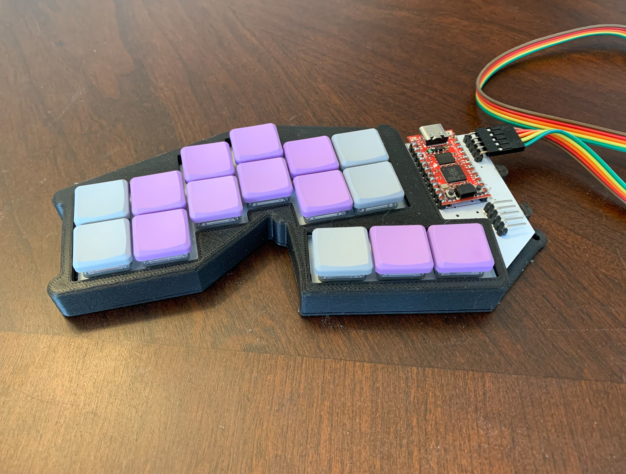
There was an earlier prototype, that was handwired, and rather fragile. This is the first version I would consider to be a usable keyboard. In the above pictures, the left half has the MCU (Pro Micro RP2040) soldered directly to a header, soldered to the PCB, and the right one uses a socket.
To build this, in addition to the PCBs, you will need
The PCB is reversable. The RP2040 board should be mounted in the labeled holes, which is always the left set when viewed from the top. The diodes are intended to be soldered to the bottom side of the board.
I have also a case design that can be 3d printed. The models are for the right side. Use your slicing software to mirror about the X axis to print the pieces for the other side.
The firmware I am using for this keyboard is in my fork of QMK.
| Qty | Value | Footprint | References |
|---|---|---|---|
| 28 | Conn_01x02_Pin | Connector_PinHeader_2.54mm:PinHeader_1x02_P2.54mm_Vertical | J1, J2, J10, J11, J12, J13, J14, J15, J16, J17, J18, J19, J20, J21, J22, J23 +12 |
| 10 | 100n | Capacitor_SMD:C_0603_1608Metric | C3, C4, C7, C8, C9, C10, C11, C12, C13, C16 |
| 3 | 1k | Resistor_SMD:R_0603_1608Metric | R5, R6, R8 |
| 2 | 10u | Capacitor_SMD:C_0603_1608Metric | C1, C2 |
| 2 | 12p | Capacitor_SMD:C_0603_1608Metric | C14, C15 |
| 2 | 1u | Capacitor_SMD:C_0603_1608Metric | C5, C6 |
| 2 | 27 | Resistor_SMD:R_0603_1608Metric_Pad0.98x0.95mm_HandSolder | R9, R10 |
| 2 | 27 | Resistor_SMD:R_0603_1608Metric | R1, R2 |
| 2 | 5.1k | Resistor_SMD:R_0603_1608Metric | R3, R4 |
| 2 | SK6812MINI-HS | davidb-keyboard-foot:SK6812-MINI-HS | D1, D2 |
| 2 | SW_SPST | Button_Switch_SMD:SW_Push_1P1T_NO_CK_KMR2 | SW1, SW2 |
| 1 | 10k | Resistor_SMD:R_0603_1608Metric | R7 |
| 1 | ABM8-272-T3 | Crystal:Crystal_SMD_Abracon_ABM8G-4Pin_3.2x2.5mm | Y1 |
| 1 | AP2112-M3.3 | davidb-keyboard-foot:AP2112M-SO8 | U2 |
| 1 | Conn_ARM_JTAG_SWD_10 | davidb-keyboard-foot:Cortex-M-Debug10 | J30 |
| 1 | RJ45 | Connector_RJ:RJ45_Amphenol_54602-x08_Horizontal | J31 |
| 1 | RP2040 | davidb-keyboard-foot:RP2040-QFN-56 | U1 |
| 1 | USB_C_Receptacle_USB2.0_14P | davidb-keyboard-foot:USB_C_Receptacle_GCT_USB4085 | J29 |
| 1 | W25Q128JVP | Package_SON:WSON-8-1EP_6x5mm_P1.27mm_EP3.4x4.3mm | U3 |


Keyboard-PCB-Replica-Project/lzIron_RP2040
이 기판은 MX 버전이며, ISO 엔터 및 Alps를 지원하지 않습니다!


SIGPLAN-AV/apple-peeler
HDMI MITM device aimed at supplying crafted EDID to make Apple sources behave


PanosEconomou/open-keyboard
A 100% from scratch open source super cool awesome keyboard that will take years to make if ever


It measures 151 × 98 mm and has 2 copper layers, 1.6 mm thick.
65 parts, built around the RP2040, W25Q128JVPIQ, SK6812MINI-HS and ABM8-272-T3. The full list of its parts is on this page, with links to each part's symbol and footprint where PCBKit's library has them.
From the tangybbq/keyboard repository on GitHub, at the commit this page was made from: the board is jolt2/jolt2-left/jolt2-left.kicad_pcb. PCBKit opens the board in the browser, with nothing to install.
Its repository states no licence, so its author keeps all rights: ask tangybbq before reusing the design.