2 layers28 × 36 mm

 takjn/GRRNble2
DIY Smartwatch using Renesas RL78/G13 MCU and RN4020 ble module with Android companion app.
GRRNble is an open-source printed circuit board by takjn, from the takjn/GRRNble repository on GitHub. It is a 2-layer board of 28 × 41 mm with 59 parts on 46 nets, routed with 604 tracks and 32 vias.
It is built around the R5F100LJAFB#10, RN4020-V/RM and DMG3415U, with the BSS138 and CUS10F30-TP among its other parts. Its parts include 16 resistors, 15 capacitors, 6 ICs, 3 transistors and 3 switches. It belongs with the radio and wireless and wearables boards of this library.


DIY Smartwatch using Renesas RL78/G13 MCU and RN4020 ble module with Android companion app.
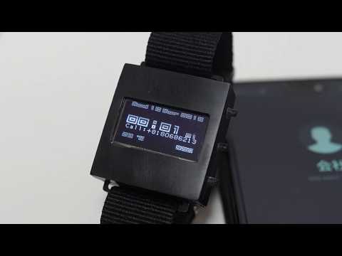
There is a KiCad project file in KiCad folder. Also, you can see the schematic pdf file in pdf folder.
All capacitors and resistors are 0805 (2012) SMD.
| Reference(s) | Value | Qty | Note |
|---|---|---|---|
| C1 | 0.47uF | 1 | I used 1.0uF insted. |
| C2, C11 | 0.1uF | 2 | |
| C3, C4 | 15pF | 2 | |
| C5, C6, C9, C10, C15, C16 | 1.0uF | 6 | |
| C7, C12, C13 | 4.7uF | 3 | |
| C8 | 2.2uF | 1 | I used 4.7uF insted. |
| R1 | 1k | 1 | |
| R2 | 12k | 1 | |
| R3 | 2k | 1 | |
| R4 | 390k | 1 | |
| R5, R6, R7, R13 | 10k | 4 | |
| R8 | 22k | 1 | |
| R9, R10 | 47k | 2 | |
| R11 | 100k | 1 | |
| R12, R14 | 100R | 2 | |
| R15 | 7K5 | 1 | |
| R16 | 2K7 | 1 | |
| D1 | CUS10F30 | 1 | |
| Q1, Q3 | DMG3415U | 2 | P-ch FET |
| Q2 | BSS138 | 1 | N-ch FET |
| SW1, SW3, SW2 | SKSCLAE010 | 3 | ALPS Side Push switch |
| U1 | R5F100LJAFB | 1 | RL78/G13 64pin |
| U2 | UGCT7525AN4 | 1 | Buzzer |
| U3 | SSD1306 | 1 | OLED 128x64 0.96 inch |
| U4 | MCP73831-2-OT | 1 | Li-Polymer Charge Management Controller |
| U5 | RN4020 | 1 | Bluetooth Low Energy module |
| U6 | MCP1703A-3302 | 1 | LDO Regulator |
| Y1 | FC-135 | 1 | EPSON 3.2 x 1.5 x 0.80mm 32.768k crystal |
| BT1 | Li-Po battery | 1 | 3.7V/40mAh |
| J1 | JST SH/1.0 6pin connector | 1 | JST 1.0mm pitch connector |
| - | JST SH/1.0 6pin cable | 1 | JST 1.0mm pitch terminal cable |
| - | FT232R / FT231X USB to serial adapter | 1 |
RN4020 can be setup with a special program and serial monitor. Open RN4020Setup folder with IDE for GR. Connect your board and select GR-Cotton from "Tools" -> "Board" in the menu. Compile the program and upload it to the board.
After uploading the sketch, select the port from "Tools" -> "Serial Port" in the menu and open Serial monitor.
Open GRRNble folder with IDE for GR. Connect your board and select GR-Cotton from "Tools" -> "Board" in the menu. Compile the program and upload it to the board.
You need to have a development environment with Android Studio to build the Android App in the Android folder.
If you don't want to build from source files, you can install the compiled app from Google Play.
| Qty | Value | Footprint | References |
|---|---|---|---|
| 6 | 1.0uF | Capacitor_SMD:C_0805_2012Metric_Pad1.15x1.40mm_HandSolder | C5, C6, C9, C10, C15, C16 |
| 4 | 10k | Resistor_SMD:R_0805_2012Metric_Pad1.15x1.40mm_HandSolder | R5, R6, R7, R13 |
| 3 | 4.7uF | Capacitor_SMD:C_0805_2012Metric_Pad1.15x1.40mm_HandSolder | C7, C12, C13 |
| 3 | SW_Push | misc:SKSC | SW1, SW2, SW3 |
| 2 | 0.1uF | Capacitor_SMD:C_0805_2012Metric_Pad1.15x1.40mm_HandSolder | C2, C11 |
| 2 | 100R | Resistor_SMD:R_0805_2012Metric_Pad1.15x1.40mm_HandSolder | R12, R14 |
| 2 | 15pF | Capacitor_SMD:C_0805_2012Metric_Pad1.15x1.40mm_HandSolder | C3, C4 |
| 2 | 47k | Resistor_SMD:R_0805_2012Metric_Pad1.15x1.40mm_HandSolder | R9, R10 |
| 2 | DMG3415U | Package_TO_SOT_SMD:SOT-23 | Q1, Q3 |
| 1 | +3V | TestPoint:TestPoint_THTPad_D1.0mm_Drill0.5mm | 3V |
| 1 | 0.47uF | Capacitor_SMD:C_0805_2012Metric_Pad1.15x1.40mm_HandSolder | C1 |
| 1 | 100k | Resistor_SMD:R_0805_2012Metric_Pad1.15x1.40mm_HandSolder | R11 |
| 1 | 12k | Resistor_SMD:R_0805_2012Metric_Pad1.15x1.40mm_HandSolder | R2 |
| 1 | 1k | Resistor_SMD:R_0805_2012Metric_Pad1.15x1.40mm_HandSolder | R1 |
| 1 | 2.2uF | Capacitor_SMD:C_0805_2012Metric_Pad1.15x1.40mm_HandSolder | C8 |
| 1 | 22k | Resistor_SMD:R_0805_2012Metric_Pad1.15x1.40mm_HandSolder | R8 |
| 1 | 2K7 | Resistor_SMD:R_0805_2012Metric_Pad1.15x1.40mm_HandSolder | R16 |
| 1 | 2k | Resistor_SMD:R_0805_2012Metric_Pad1.15x1.40mm_HandSolder | R3 |
| 1 | 32.768k | Crystal:Crystal_SMD_G8-2Pin_3.2x1.5mm_HandSoldering | Y1 |
| 1 | 390k | Resistor_SMD:R_0805_2012Metric_Pad1.15x1.40mm_HandSolder | R4 |
| 1 | 7K5 | Resistor_SMD:R_0805_2012Metric_Pad1.15x1.40mm_HandSolder | R15 |
| 1 | A2 | TestPoint:TestPoint_Pad_D1.0mm | A2 |
| 1 | A3 | TestPoint:TestPoint_Pad_D1.0mm | A3 |
| 1 | A4 | TestPoint:TestPoint_Pad_D1.0mm | A4 |
| 1 | A5 | TestPoint:TestPoint_Pad_D1.0mm | A5 |
| 1 | A6 | TestPoint:TestPoint_THTPad_D1.0mm_Drill0.5mm | A6 |
| 1 | BSS138 | Package_TO_SOT_SMD:SOT-23 | Q2 |
| 1 | BUZZER | misc:BZ7025_3pin | U2 |
| 1 | Battery_Cell | misc:BatteryPad | BT1 |
| 1 | CUS10F30 | Diode_SMD:D_SOD-323_HandSoldering | D1 |
| 1 | D6 | TestPoint:TestPoint_THTPad_D1.0mm_Drill0.5mm | D6 |
| 1 | GND | TestPoint:TestPoint_THTPad_1.0x1.0mm_Drill0.5mm | GND |
| 1 | JST_SH_06 | JST-SH:JST-SM-06B-SRSS-TB | J1 |
| 1 | Jumper_NO_Small | Jumper:SolderJumper-2_P1.3mm_Open_RoundedPad1.0x1.5mm | JP1 |
| 1 | LOGO | misc:logo | G*** |
| 1 | MCP1703A-3302_SOT23 | Package_TO_SOT_SMD:SOT-23 | U6 |
| 1 | MCP73831-2-OT | Package_TO_SOT_SMD:SOT-23-5 | U4 |
| 1 | R5F100LJAFB | Package_QFP:LQFP-64_10x10mm_P0.5mm | U1 |
| 1 | RN4020 | library:RN4020 | U5 |
| 1 | SCL | TestPoint:TestPoint_THTPad_D1.0mm_Drill0.5mm | SCL |
| 1 | SDA | TestPoint:TestPoint_THTPad_D1.0mm_Drill0.5mm | SDA |
| 1 | SSD1306 | SSD1306:SSD1306 | U3 |
It measures 28 × 41 mm and has 2 copper layers, 1.6 mm thick.
59 parts, built around the R5F100LJAFB#10, RN4020-V/RM, DMG3415U and BSS138. The full list of its parts is on this page, with links to each part's symbol and footprint where PCBKit's library has them.
From the takjn/GRRNble repository on GitHub, at the commit this page was made from: the board is KiCad/GRRNble.kicad_pcb. PCBKit opens the board in the browser, with nothing to install.
Its repository states no licence, so its author keeps all rights: ask takjn before reusing the design.

Tomoshibi-technology/RCJ-Japan2024-Circuit
RoboCup JapanOpen 2024とEindohoven 2024に向けての回路開発

kcuzner/rt-soldering-iron
Soldering iron driver board for Weller RT tips. A work in progress. Firmware in rust.

hnz1102/breadboard-power-alligator
BREAD BOARD POWER ALLIGATOR : Power Supply for Bread-Board

hnz1102/EEW-display
ESP32-S3 firmware for a small earthquake-information display. It shows recent earthquakes and emergency earthquake warnings (緊急地震速報, EEW) from [P2P地震情報](https://www.p2pquake.net/), draws the epicenters on a Google map…


LeHack/SPSP
Particulate matter pollution monitoring system (:poland: System Pomiaru Stężenia Pyłu w powietrzu)