
4 layers95.6 × 73.6 mm

 swift502/Krteq15
Low profile ortholinear keyboard
Krteq is an open-source printed circuit board by swift502, from the swift502/Krteq repository on GitHub, published under the CC0-1.0 licence. It is a 2-layer board of 228.6 × 114.3 mm with 201 parts on 131 nets, routed with 2,983 tracks and 459 vias.
It is built around the IS31FL3733B-QFLS4-TR, KS-2P02B01-02 and 23-23B/R6GHBHC-A30/2A, with the 1N4148W and T520A226M010ATE080 among its other parts. Its parts include 122 diodes, 61 switches, 8 capacitors, 5 resistors and 3 connectors. It belongs with the keyboards and input boards and the RP2040 boards of this library.


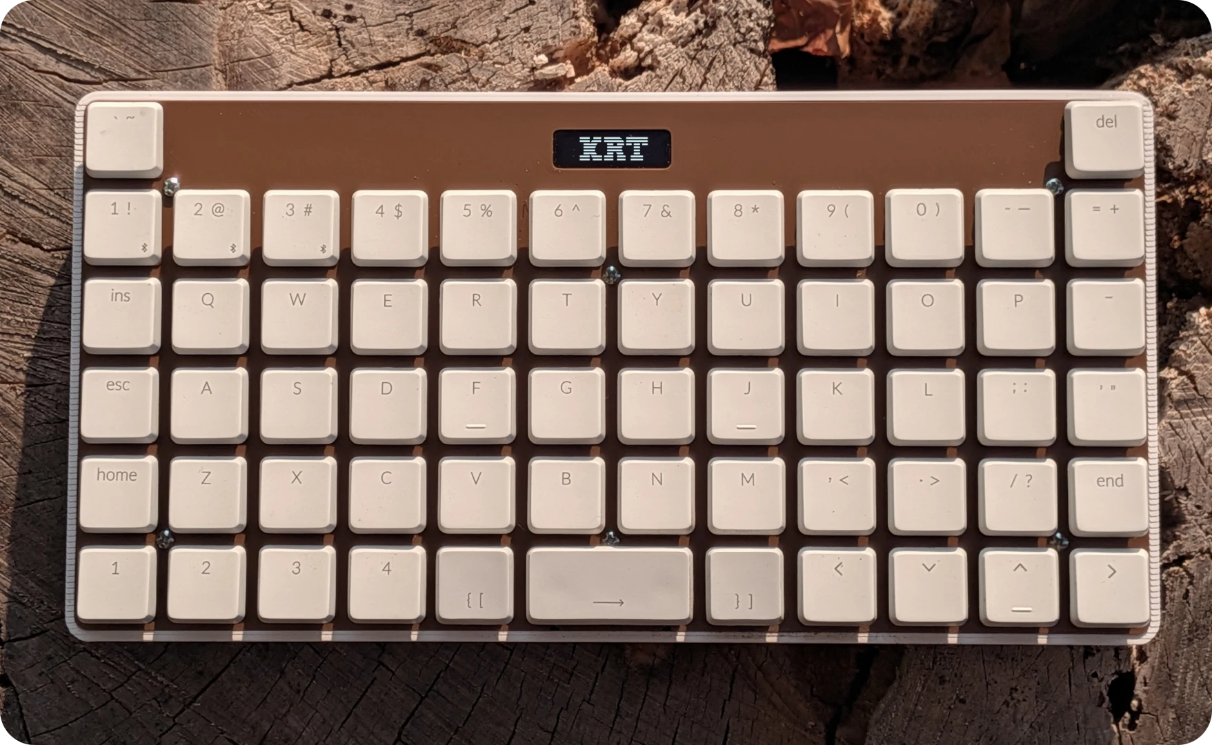


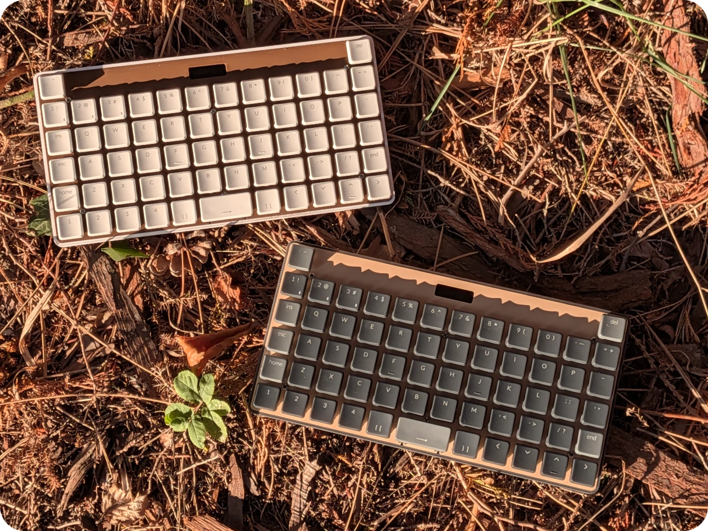
An extended 5x12 keyboard with 2 extra keys. Intended for ortho layouts with a shifted number row, allowing for the placement of the delete and tilde keys above their usual spots.
Krteq is a successor to Krtkus, learning from its lessons to make a design that's better encapsulated and much more complete.
Connecting the keyboard to usevia.app requires manually uploading the design file in the design tab.
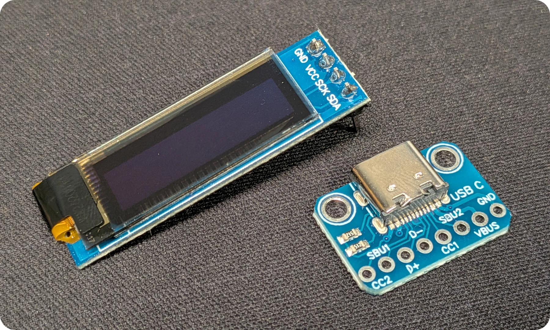
The USB-C breakout board is expected to match the specs of the Adafruit USB-C breakout board with two M2.5 screw holes 15.24mm apart, 2.54mm from the front edge, and built-in resistors for the CC lines.
The OLED display module is expected to be a 128x32 I2C OLED screen. These screens are not very standardized, so the PCB cutout is generous to fit modules with slightly different dimensions. Any OLED roughly equal or less than 38x12mm should fit, and at most require slight modifications to the display cutout in the plate.
The Kicad 10 project can be found in source/kicad. All parts are SMD, the PCB is intended to be ordered with pre-assembled SMD components for an easier, although more expensive build process.
To generate fabrication files, open the Kicad project and use an export plugin provided by the PCB manufacturer you want to order from. The order process is then highly dependent on the manufacturer.
| Part | Package | Manufacturer Part Number |
|---|---|---|
| Switch diode | SOD-123 | 1N4148W |
| Switch socket | SMD | KS-2P02B01-02 |
| RGB LED | SMD-4P,3.2x1.3mm | 23-23B/R6GHBHC-A30/2A |
| RGB driver | QFN-48-EP(6x6) | IS31FL3733B-QFLS4-TR |
| 0.1µF capacitor | 0402 | CL05B104KO5NNNC |
| 0.47µF capacitor | 0603 | CL10B474KA8NNNC |
| 22µF/10V capacitor | CASE-A-3216-18(mm) | T520A226M010ATE080 |
| 2kΩ resistor | 0603 | 0603WAF2001T5E |
| 20kΩ resistor | 0603 | 0603WAF2002T5E |
| 100kΩ resistor | 0603 | 0603WAF1003T5E |
Case blend file can be found in source/Krteq.blend. It's designed non-destructively, so it should be easy to modify if needed.
STL files for 3D printing can be found in production/stl. Recommended printing parameters are:
The plate also has a "keychron" variant, which adjusts stabilizer cutouts for their non-standard triangular stem design.
QMK/VIA setup with a few custom features:
Some functionality can be overridden in a user keymap config.h:
// Layer which forces a preview of the "Indicators" screen
#define INDICATORS_SHOW_LAYER 1

// Replace the scroll lock indicator with three letter
// string to denote custom script functionality
#define INDICATORS_SCROLL_LABEL "ACC"

// Layer (and above) which shows the "Input lock" screen
#define INPUT_LOCK_LAYER 4In QMK, user keymaps can completely override oled rendering via oled_task_user(). However, Krteq also exposes its custom screen system, where screen interaction is done via the KRT_SCR keycode. Hooking into this system is preferred as it ensures that other built-in system screen features continue to work properly.
Here's a minimal example of a custom screen definition in a user keymap:
// 1. Create a render function
static void custom_screen_render(void)
{
    oled_write_P(PSTR("Hello world"), false);
}

// 2. Construct a screen instance
static const krteq_screen_t custom_screen = {
    .name = "Custom screen",
    .start = custom_screen_render,
};

// 3. Override built-in screen list
const krteq_screen_t *const user_screens[] = {
    &custom_screen
};
Here's a table of fields and callbacks available for screens to implement:
| Property | Description |
|---|---|
.name | Display name string |
.init | Runs once on keyboard start-up |
.start | Runs every time the screen is activated |
.update | Runs every OLED task cycle when screen is active |
.key_event | Key press event |
You can combine custom screens with the built-in ones. You can reshuffle them, remove some and add your own. The built-in screen list goes as follows:
const krteq_screen_t *const user_screens[] = {
    &krteq_screen_indicators,
    &krteq_screen_bongo_cat,
    &krteq_screen_starfield,
    &krteq_screen_waves,
    &krteq_screen_cursor,
    &krteq_screen_game_of_life,
    &krteq_screen_system_info
};Install:
Run the compile script:
python source/scripts/qmk_compile.pyFor the initial flash, hold the BOOTSEL button while connecting the Pico to a computer to have it show up as a storage device, then copy the compiled firmware file over to it.
Once flashed, you can trigger the bootloader mode again by simply pressing the LShift + RShift + B key combination.
| Qty | Value | Footprint | References |
|---|---|---|---|
| 61 | GATERON Low Profile Switch Hot-swap Socket | Krteq:Gateron_KS-33 | SW1, SW2, SW10, SW11, SW12, SW13, SW14, SW15, SW16, SW17, SW18, SW19, SW20, SW21, SW22, SW23 +45 |
| 61 | Reverse Mount LED ARGB | Krteq:ReverseMount_LED | D101, D102, D103, D104, D105, D106, D107, D108, D109, D110, D111, D112, D113, D114, D115, D116 +45 |
| 61 | Switch Diode | Krteq:D_SOD-123 | D1, D2, D10, D11, D12, D13, D14, D15, D16, D17, D18, D19, D20, D21, D22, D23 +45 |
| 4 | 0.47µF | Capacitor_SMD:C_0603_1608Metric | C1, C2, C3, C4 |
| 3 | 0.1µF | Capacitor_SMD:C_0402_1005Metric | C5, C6, C7 |
| 2 | 100kΩ | Resistor_SMD:R_0603_1608Metric | R3, R4 |
| 2 | 2kΩ | Resistor_SMD:R_0603_1608Metric | R1, R2 |
| 1 | 20kΩ | Resistor_SMD:R_0603_1608Metric | R5 |
| 1 | 22µF/10V | Krteq:CASE-A-3216-18(mm) | C8 |
| 1 | LED Driver | Krteq:QFN-48_6x6mm | U71 |
| 1 | OLED 128x32 | Krteq:Interface_1x04_P2.54mm | J3 |
| 1 | Pico Test Points | Krteq:Interface_1x03_P2.54mm | J2 |
| 1 | Raspberry Pi Pico | Krteq:RaspberryPi_Pico | A1 |
| 1 | USB Breakout Board | Krteq:Interface_1x04_P2.54mm | J1 |
It measures 228.6 × 114.3 mm and has 2 copper layers, 1.6 mm thick.
201 parts, built around the IS31FL3733B-QFLS4-TR, KS-2P02B01-02, 23-23B/R6GHBHC-A30/2A and 1N4148W. The full list of its parts is on this page, with links to each part's symbol and footprint where PCBKit's library has them.
From the swift502/Krteq repository on GitHub, at the commit this page was made from: the board is source/kicad/Krteq/Krteq.kicad_pcb and its schematic source/kicad/Krteq/Krteq.kicad_sch. PCBKit opens the board in the browser, with nothing to install.
Its repository publishes it under the CC0-1.0 licence: you may reuse it on that licence's terms (keep the author's notice, and for a copyleft licence share your changes alike).

mburger89/SMK_macro_pad
4x4 wireless macro pad — RP2040 + Raspberry Pi RM2. KiCad project generated from Python; includes a 42%-smaller 'mini' variant with back-mounted electronics.

AronTech1/Galatea-75-wireless-mechanical-keyboard
Galatea: 75% wireless mechanical keyboard with a 5" IPS display, per-key LEDs, rotary encoder, voice button and I²S microphone.


fossasia/pslab-hardware
PSLab Hardware Design and Schematics https://pslab.io

pierrechevalier83/ferris
A low profile split keyboard designed to satisfy one single use case elegantly


MickiusMousius/Rolio46Keyboard
A split wireless keyboard based on the Corne and Sofle