2 layers385 × 127.3 mm

 swampmonster/plonck9
An attempt at making a planck-compatible pcb with bluetooth
Plonck is an open-source printed circuit board by swampmonster, from the swampmonster/plonck repository on GitHub. It is a 2-layer board of 228.6 × 78.7 mm with 132 parts on 97 nets, routed with 1,014 tracks and 140 vias.
It is built around the SRV05-4, 1N4148W and 19-217/BHC-ZL1M2RY/3T, with the KT-0603R, SS14 and TYPE-C-31-M-12 among its other parts. Its parts include 51 diodes, 9 resistors, 5 capacitors, 4 ICs and 3 connectors. It belongs with the radio and wireless boards and the nRF52 and nRF5x boards of this library.


An attempt at making a planck-compatible pcb with bluetooth
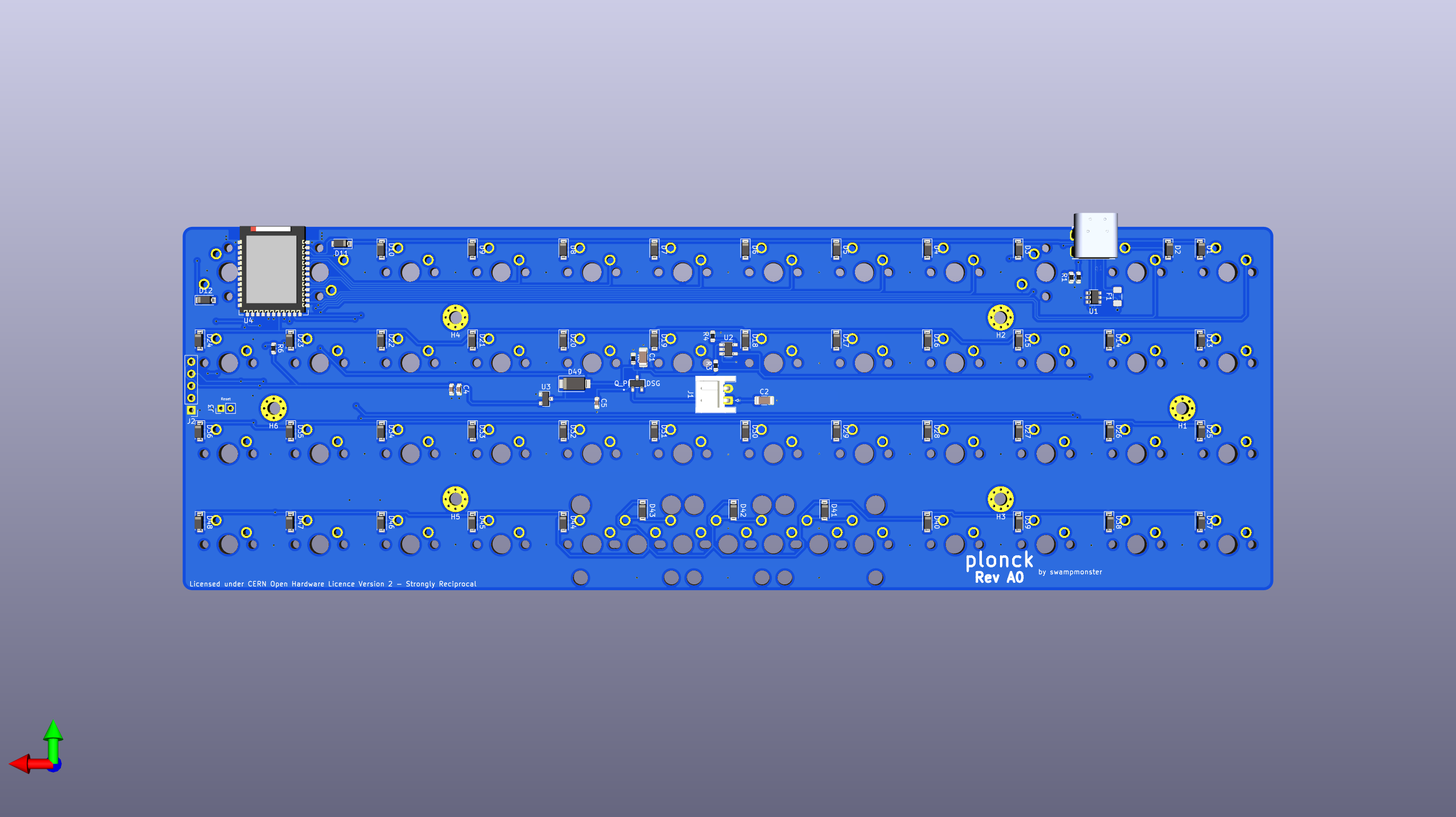
I've received and built this version and it works fine but i made the mistake of wiring up the GND and VBUS pins on the ESD chip incorrectly.
Thankfully those are the middle pins and simply desoldering and turning the chip around solves the problem.
Update: Finally had time to test the load sharing circuitry and i had the pinout of the mosfet setup incorrectly which requires bodge wires to fix.
If you are looking to get boards made from this revision you need to be aware of this but my recommendation would be to wait for the next one.
This should address all the issues in A0 while also adding some features that were not previously present such as:
Boards have been ordered but not yet received so production is still not recommended.
The project is licensed under CERN-OHL-S (see LICENSE file) with the exceptions of:
Huge shoutout to 4pplet for tons of advice and help.
| Qty | Value | Footprint | References |
|---|---|---|---|
| 48 | 1N4148W | Diode_SMD:D_SOD-123 | D1, D2, D10, D11, D12, D13, D14, D15, D16, D17, D18, D19, D20, D21, D22, D23 +32 |
| 48 | MX-NoLED | MX_Alps_Hybrid:MX-1U-NoLED | MX1, MX2, MX10, MX11, MX12, MX13, MX14, MX15, MX16, MX17, MX18, MX19, MX20, MX21, MX22, MX23 +32 |
| 6 | MountingHole | MountingHole:MountingHole_2.7mm_M2.5_Pad_TopBottom | H1, H2, H3, H4, H5, H6 |
| 3 | MX-NoLED | MX_Alps_Hybrid:MX-2U-ReversedStabilizers-NoLED | MX49, MX50, MX51 |
| 2 | 10k | Resistor_SMD:R_0603_1608Metric | R4, R6 |
| 2 | 4.7uF | Capacitor_SMD:C_0603_1608Metric | C3, C5 |
| 2 | 47uF | Capacitor_SMD:C_1206_3216Metric | C1, C2 |
| 2 | 5.1k | Resistor_SMD:R_0603_1608Metric | R1, R2 |
| 1 | 100k | Resistor_SMD:R_0603_1608Metric | R5 |
| 1 | 19-217/BHC-ZL1M2RY/3T | LED_SMD:LED_0603_1608Metric | D51 |
| 1 | 1uF | Capacitor_SMD:C_0603_1608Metric | C4 |
| 1 | 2M | Resistor_SMD:R_0603_1608Metric | R9 |
| 1 | 33 | Resistor_SMD:R_0603_1608Metric | R7 |
| 1 | 470 | Resistor_SMD:R_0603_1608Metric | R3 |
| 1 | 806k | Resistor_SMD:R_0603_1608Metric | R8 |
| 1 | Battery_connector | SM02B-SRSS-TB_LF__SN_:SM02B-SRSS-TB(LF)(SN) | J2 |
| 1 | Conn_01x06 | Connector:Tag-Connect_TC2030-IDC-NL_2x03_P1.27mm_Vertical | J3 |
| 1 | KT-0603R | LED_SMD:LED_0603_1608Metric | D37 |
| 1 | Q_PMOS_GSD | ul_SI2301CDST1GE3:SI2301CDS-T1-GE3 | Q1 |
| 1 | SMD Fuse Fast Blow 500mA | Fuse:Fuse_1206_3216Metric | F1 |
| 1 | SRV05-4 | Package_TO_SOT_SMD:SOT-23-6 | U1 |
| 1 | SS14 | Diode_SMD:D_SMA | D50 |
| 1 | SW_Push | Button_Switch_SMD:SW_Push_SPST_NO_Alps_SKRK | SW1 |
| 1 | TP4054-42-SOT25-R | Package_TO_SOT_SMD:TSOT-23-5 | U2 |
| 1 | TYPE-C-31-M-12 | Connector_USB:USB_C_Receptacle_HRO_TYPE-C-31-M-12 | J1 |
| 1 | XC6206PxxxMR-Regulator_Linear | Package_TO_SOT_SMD:SOT-23 | U4 |
| 1 | nRF52840_holyiot_18010 | holyiot-18010:nRF52840_holyiot_18010_HS_simple | U3 |


joshajohnson/louise
A project between Josh and RiotPunch to build a 75% alice keyboard with a southpaw numpad.

florolf/lab-automation
Plugs into relay and can be used to provide switchable 5V USB power to downstream devices.


elagil/net-bmp
An Ethernet-connected SWD/JTAG debug adapter (blackmagic probe)

McMaster-Rocketry-Team/VLF4r2
PCB schematics and layout for Void Lake Fusion 4 Avionics
It measures 228.6 × 78.7 mm and has 2 copper layers, 1.6 mm thick.
132 parts, built around the SRV05-4, 1N4148W, 19-217/BHC-ZL1M2RY/3T and KT-0603R. The full list of its parts is on this page, with links to each part's symbol and footprint where PCBKit's library has them.
From the swampmonster/plonck repository on GitHub, at the commit this page was made from: the board is plonck.kicad_pcb and its schematic plonck.kicad_sch. PCBKit opens the board in the browser, with nothing to install.
Its repository states no licence, so its author keeps all rights: ask swampmonster before reusing the design.