Skip to the content
PCBKitNew board
2 layers290.5 × 113.3 mmKing44 hand, the printed circuit board in 3D

King44 Optical Split Keyboard with KeyChron Switches, TrackPoint and Haptic Feedback

Size
290.5 × 113.3 mm
Copper layers
2
Thickness
1.6 mm
Parts
178
Nets
171
Pads
866
Tracks, vias
3,172, 591
Pours
4
Routed
Yes
KiCad
KiCad 9.0 (file 20241229)
Created
7 Jun 2025
Updated
8 Jun 2025

Overview

King44 hand is an open-source printed circuit board by superami-code, from the superami-code/King44 repository on GitHub. It is a 2-layer board of 290.5 × 113.3 mm with 178 parts on 171 nets, routed with 3,172 tracks and 591 vias.

It belongs with the keyboards and input boards of this library.

README

README.md

King44

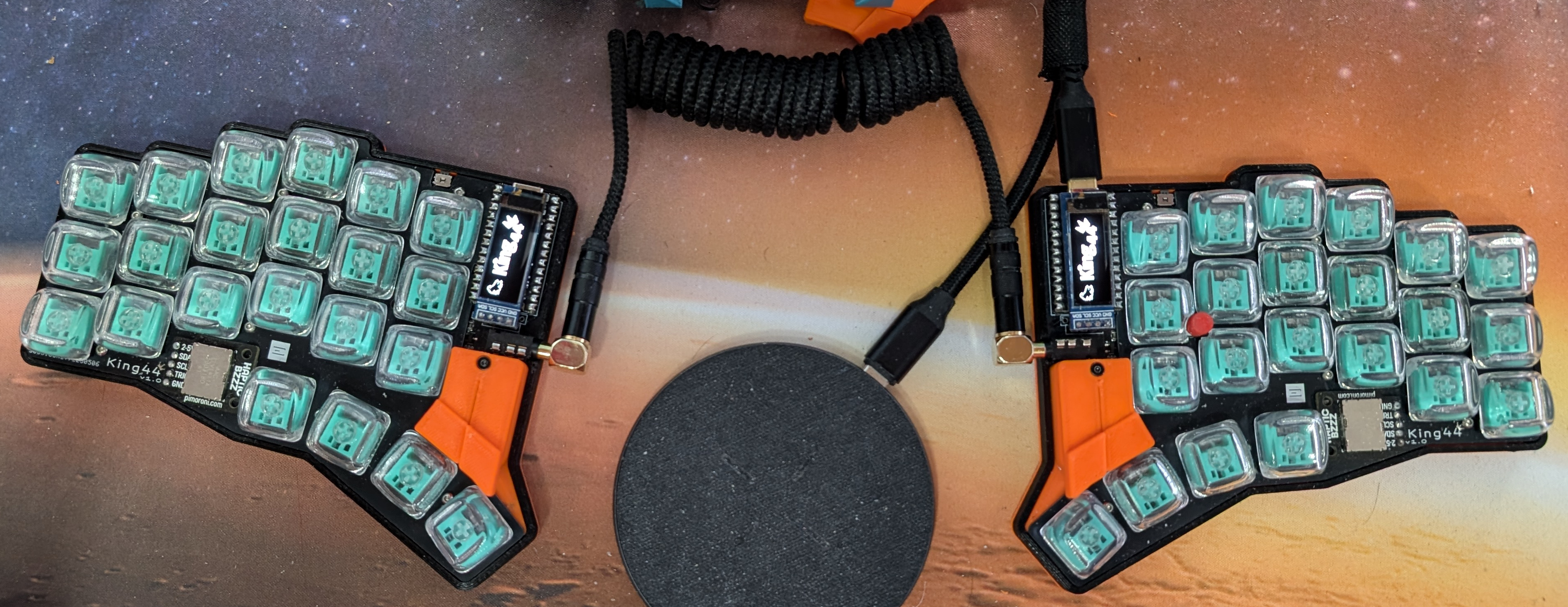
King44 in wide glory

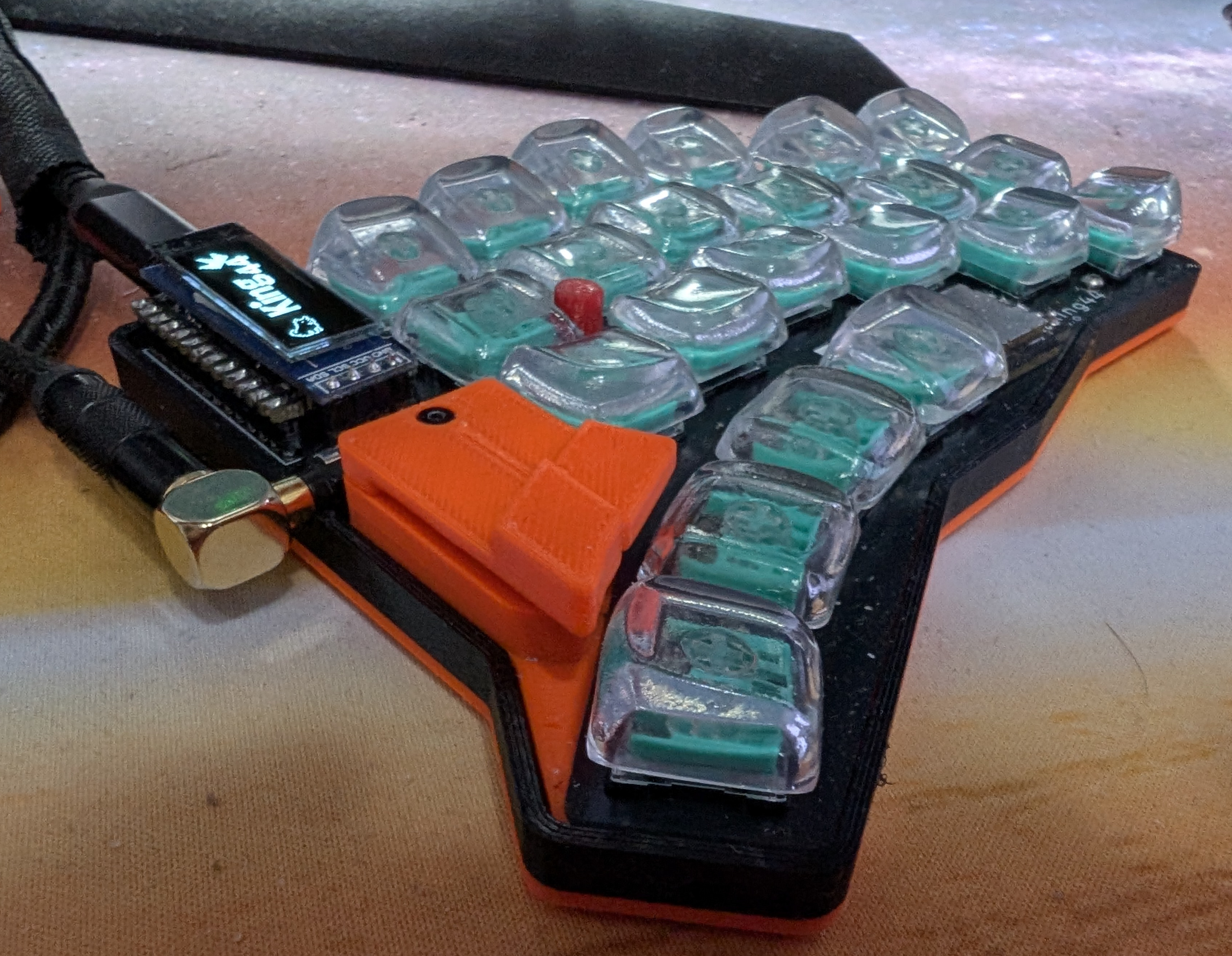
This is a low profile optical keyboard, based on the KeyChron switches with trackpoint, haptic feedback on layer switches and mod keys, per of the key sculpted key caps.

King44 Close-up

I still have extra IR/PT parts if anyone needs some.

While I really like the feel of the keys and the position and feel of the trackpoint, the process of getting the protoytpe working was tough to say the least. I am using a T420 trackpoint and the mint key switches, but checking now It would appear that they have been discontinued. :( I have enough for a second keyboard and that is it.

Finding a supply of the IR/PT pair that is small enough was near impossible. In the end I couldn't get them to JLCPCB and had to source a batch directly from the manufacturer and hand solder them. I made the mistake of having many of the parts placed and soldered by JLCPCP. I should have just gotten a stencil to begin with. Hand soldering the IR/PT sensors was tedious and I had many issues. I would not recommend the optical sensors unless you have a stencil and reflow capabilities. Regular soldering temps can damage the lenses.

The second issue was I neglected to consider the rise and fall time of the IR parts. The IR transmitter should ideally always be on, and the receiver probably as well. This though would necessitate using a multiplexer or direct pin reading, but that would mean dropping support for the trackpoint, I2C (haptic + OLED) or both.

I really enjoy the haptic feedback and RGB layers. It makes layer switches more defined and obvious. I have not done too much with it yet, but I am looking forward to playing around with it some more.

The AUTO mouse layer is really nice. It allows me to use the standard thumb keys as mouse buttons, when using the trackpoint. The position of these buttons is much more ergonomic.

Manufacturing

  • PCB 1.6mm
  • Plate 1.2mm
  • Trackpoint
    • harvested from an T420 keyboard
    • trackpoint uses the smaller threaded M2 screws.
      • I could not find a source for these and standard M2 will not fit.
      • My solution was to drill out the holes and tap M2.5 threads with an 8€ drill and tap kit

Issues found in v1.0

  • Mounting Plate

    • Tolerances of the key cutouts are too loose.
      • Should be manufactured using with tighter tolerances
      • Looseness of keys can be addressed with a small, thin piece of plastic or paper behind the clear plastic clips to tighten things up
    • Right Mounting Hole for mouse buttons conflict with PCB Plate
    • Power and reset buttons are too thick to be between the mounting plate and PCB
      • Maybe move to next to the mouse buttons
      • or cutout the plate
      • Maybe place on botton to allow for better containment in case
    • MCU is too close to plate, and needs more space
    • Haptic Engine cutout
      • Remove from PCB
      • Increase size on plate
      • Add Mill-Max Pin sockets to base PCB
    • CAP is too high for between boards, move or cut-out from plate
    • trackpoint hole is too small, needs to be 5-5.5mm
  • Mouse buttons might be better closer to the keys

    • They need a diode per key, as on any standard mechanical keyboard
    • They need to use the two outside PINS if the logic High model is retained
    • After using AUTO mouse layer, the current locations are definitely less than ergonomic, requiring too much hand movement
    • I plan on working on better solution, potentially with a pivot and you press forward of raise your thumb for mouse buttons.
  • trackpoint

    • hole in PCB Plate appears to be too small
    • mounting holes should fit M2.5 to allow the drilled and tapped solution if the smaller M2's can't be found in the future.
  • IR Receiver (PT) marking is on the wrong side, which would lead to an upside down disfunctional receiver

    • PT parts have thus been place with the markings opposite the silkscreen.

    • This may actually necessitate a swapping of the pads for manufacturing

    • Need to also review the datasheets to determine the correct orientation for automated manufacturing

  • Helios 0xCB

    • Both Hands
      • P1 is actually GND, and needs to be connected as such
      • Switch P1 for P4
      • Power control circuit for touchstick connects touchstick VCC to GND.
        • Current prototype just bypasses the control circuit and always provides VCC to the trackpoint daughter board
    • Right Hand
      • SDA + SCL are incorrect on right hand (left board) and need to be swapped
      • Right ground pin of Helios is not connected to anything
    • Interboard communication for the RP2040 should be done with one wire and the same PIN on both devices
      • Currently there is a software workaround
      • This would free up one PIN for other uses.
  • QMK is active LOW, but the logic was built around active high

    • The use of an N-Channel MOSFET in the protoytpe required a custom matrix.c to allow for active HIGH ROW signals
      • a P-Channel MOSFET could resolve this, BUT would require extra components for the mouse buttons, as they also rely on the active HIGH currently
    • Another option would be to rework IR Receiver to pull up instead of down.
      • Currently the IR receiver is needed to pull the circuit down and prevent key presses
    • maybe next time use a input multiplexer, or CPU with more PINS to allow
      • constant on IR LED would use more power, but provide at least 10µs faster response times
  • trackpoint

    • Reset CAP wrong -- should connect reset to VCC (NOT GND as it is currently)
  • TRRS

    • I stuck with TRRS as I had a nice custom coiled cable from my Span, but I Think it's time to start using USB-C other more common cable
    • That would make it easier to get or make custom cables
    • Remove the short circuit potential when a cable is disconnected while the board is on.

Parts

  • BSS138 with pulldown for base SOT23 SMD

    • 2N7002 / C8545
  • LED

    • WS2812B-2020 / C965555
  • Resistors + Caps

    • RS - 0805 - 220 # lso used for SOT transistors
      • 0805W8F2200T5E / C17557
    • R4.7k - 0805 - 4.7k
      • 0805W8F4701T5E / C17673
    • R100k - 0805 - 100k
      • 0805W8F1003T5E / C149504
    • C2.2u
      • CL21A225KBQNNNE / C377773
  • IR Sender

    • AL-S0602IRC-VI-10P9 / C9900048597
  • IR Receiver

    • AL-S0602PTB-VI-1016 / C9900048594
  • TRRS PJ-320a

    • C2884926
  • Power Switch

    • ALPSALPINE SSSS811101 / C109335
  • Reset Button

    • EVQPUA02K / C128539
  • Buzzer

    • Pimoroni - DRV2605L Linear Actuator

Hardware

  • 18x mounting PCB
    • m2 spacer 1.3mm (3D printed ./output/fusion360/spacer_large.3mf)
    • m2 mounting screws 8mm
    • m2 threaded inserts in case
    • m2 screws (8.1mm threaded + head)
      • 1.2mm PCB Plate
      • 1.3mm spacer
      • 1.6mm PCB
      • 2mm Threaded insert
    • m2 6mm for mouse button cap
  • 2x mounting trackpoint
    • m2.5 6mm screws
      • 1.6mm PCB
      • 1 mm spacer
      • 1.3mm trackpoint
      • 1.5mm nutFRC0805F2100 TS

Parts

178
QtyValueFootprintReferences
62smd_805F-SMD1, F-SMD2, F-SMD10, F-SMD11, F-SMD12, F-SMD13, F-SMD14, F-SMD15, F-SMD16, F-SMD17, F-SMD18, F-SMD19, F-SMD20, F-SMD21, F-SMD22, F-SMD23 +46
44Keychron_Optical_SwitchF-Keychron_Optical_Switch1, F-Keychron_Optical_Switch2, F-Keychron_Optical_Switch10, F-Keychron_Optical_Switch11, F-Keychron_Optical_Switch12, F-Keychron_Optical_Switch13, F-Keychron_Optical_Switch14, F-Keychron_Optical_Switch15, F-Keychron_Optical_Switch16, F-Keychron_Optical_Switch17, F-Keychron_Optical_Switch18, F-Keychron_Optical_Switch19, F-Keychron_Optical_Switch20, F-Keychron_Optical_Switch21, F-Keychron_Optical_Switch22, F-Keychron_Optical_Switch23 +28
20ceoloide:mounting_hole_npthF-MH1, F-MH2, F-MH3, F-MH4, F-MH5, F-MH10, F-MH11, F-MH12, F-MH13, F-MH14, F-MH15, F-MH16, F-MH17, F-MH18, F-MH19, F-MH20 +4
12SOT-23SOT-23F-sot23-1, F-sot23-2, F-sot23-3, F-sot23-4, F-sot23-5, F-sot23-6, F-sot23-7, F-sot23-8, F-sot23-9, F-sot23-10, F-sot23-11, F-sot23-12
4padsB-PAD2, B-PAD4, F-PAD1, F-PAD3
4crownB-LOGO3, B-LOGO6, F-LOGO2, F-LOGO5
4SW_D2FC_OMRSW_D2FC_OMRF-SW_D2FC_7N1, F-SW_D2FC_7N2, F-SW_D2FC_7N3, F-SW_D2FC_7N4
2zzkeeb:Hole_Breakaway-TabsRB1, RB2
2trackpoint_mount_t430B-TP1, B-TP2
2ceoloide:battery_connector_jst_ph_2JST1, JST2
2ceoloide:trrs_pj320aF-TRRS1, F-TRRS2
22040undefined-_1, undefined-_2
2ceoloide:display_nice_viewDISP1, DISP3
2ceoloide:reset_switch_smd_sideRST1, RST2
2ceoloide:power_switch_smd_sidePWR1, PWR2
2ceoloide:utility_ergogen_logoF-LOGO1, F-LOGO4
2ceoloide:display_ssd1306F-DISP2, F-DISP4
24.7ksmd_805R_4.7k_10, R_4.7k_11
2JST_GH_BM05B-GHS-TBT_1x05-1MP_P1.25mm_VerticalJST_GH_BM05B-GHS-TBT_1x05-1MP_P1.25mm_VerticalCONN1, CONN2
2Jumperlib:JumperR_RGB1, RGB1
2Pimoroni Haptic Buzz DRV2605L DriverPimoroni Haptic Buzz DRV2605L Driverpimoroni_haptic1, pimoroni_haptic2

Questions

How big is the King44 hand PCB?

It measures 290.5 × 113.3 mm and has 2 copper layers, 1.6 mm thick.

What parts does the King44 hand use?

178 parts. The full list of its parts is on this page, with links to each part's symbol and footprint where PCBKit's library has them.

Where can I download the King44 hand KiCad files?

From the superami-code/King44 repository on GitHub, at the commit this page was made from: the board is output/pcbs/king44_hand.kicad_pcb. PCBKit opens the board in the browser, with nothing to install.

Can I use the King44 hand design in my own project?

Its repository states no licence, so its author keeps all rights: ask superami-code before reusing the design.

More from superami-code/King44

2
  • 2 layers290.5 × 113.3 mmKing44, the printed circuit board in 3D

    King44

    superami-code/King44

    King44 Optical Split Keyboard with KeyChron Switches, TrackPoint and Haptic Feedback

    312 parts2
  • 2 layers143.8 × 113.3 mmKing44 plate, the printed circuit board in 3D

    King44 plate

    superami-code/King44

    King44 Optical Split Keyboard with KeyChron Switches, TrackPoint and Haptic Feedback

    13 parts2

Similar boards

  • 2 layers132.7 × 37.3 mmSun sensor test, the printed circuit board in 3D

    Sun sensor test

    rgw3d/1KCubeSat_Hardware

    Hardware design files for my $1000 CubeSat.

    178 parts158GPL-3.0
  • 2 layers99.4 × 53.7 mmNO2C, the printed circuit board in 3D

    NO2C

    turboedge/SpeedyBoards

    EMS boards powered by Speeduino

    178 parts110GPL-2.0
  • 2 layers100 × 85 mmVNA, the printed circuit board in 3D

    VNA

    profdc9/VNA

    Vector Network Analyzer based on the STM32F103C8T6 bluepill

    178 parts93
  • 2 layers312 × 96.1 mmNt660, the printed circuit board in 3D

    Nt660

    evyd13/nt-series

    Replacement PCBs for the FC660m, FC750r and FC980m.

    178 parts56CC-BY-SA-4.0
  • 2 layers275.5 × 105.6 mmCorne cherry, the printed circuit board in 3D

    Corne cherry

    waffle87/protoncrkbd

    Proton-C compatible crkbd PCB

    178 parts32MIT
  • 2 layers242 × 60 mmRoothubs, the printed circuit board in 3D

    Roothubs

    gkiefer/home2l

    The Home2Ls - Smart Tools for a Private Home

    178 parts21
  • 2 layers69.2 × 107 mmTides2 v40, the printed circuit board in 3D

    Tides2 v40

    mort13/clandestine_circuitry

    Collection of diy synth projects

    178 parts12GPL-3.0
  • 2 layers182.8 × 158.9 mmErgoDOX, the printed circuit board in 3D

    ErgoDOX

    se7en9057/ErgoDOX-2.0

    An updated ErgoDox 2 handed keyboard

    178 parts7