2 layers290.5 × 113.3 mm
King44 hand
superami-code/King44
King44 Optical Split Keyboard with KeyChron Switches, TrackPoint and Haptic Feedback
178 parts2
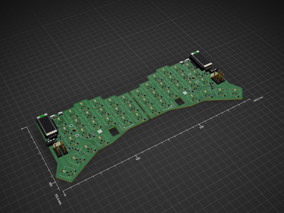
 superami-code/King442
King44 Optical Split Keyboard with KeyChron Switches, TrackPoint and Haptic Feedback
King44 is an open-source printed circuit board by superami-code, from the superami-code/King44 repository on GitHub. It is a 2-layer board of 290.5 × 113.3 mm with 312 parts on 171 nets, routed with 3,000 tracks and 560 vias.
Its parts include 64 resistors, 44 diodes and 2 capacitors. It belongs with the keyboards and input boards of this library.
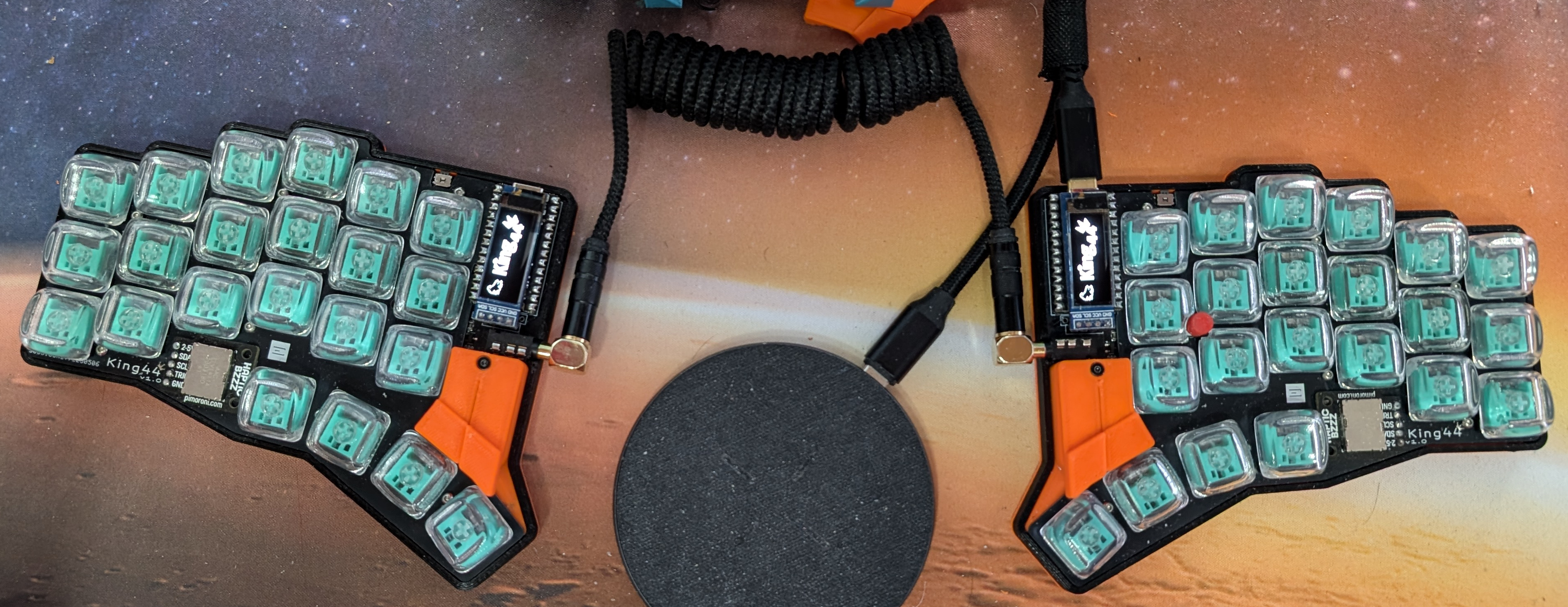
This is a low profile optical keyboard, based on the KeyChron switches with trackpoint, haptic feedback on layer switches and mod keys, per of the key sculpted key caps.
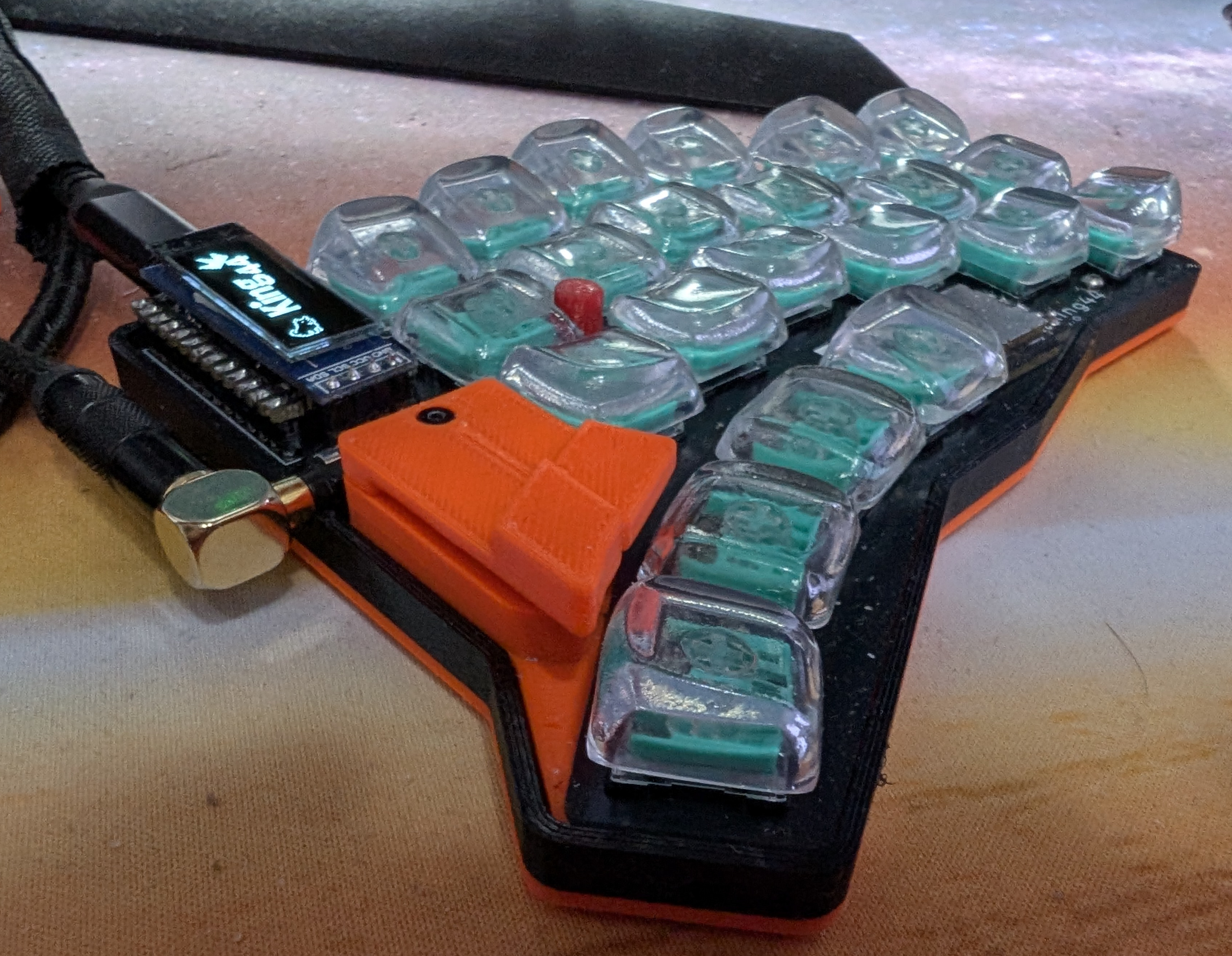
I still have extra IR/PT parts if anyone needs some.
While I really like the feel of the keys and the position and feel of the trackpoint, the process of getting the protoytpe working was tough to say the least. I am using a T420 trackpoint and the mint key switches, but checking now It would appear that they have been discontinued. :( I have enough for a second keyboard and that is it.
Finding a supply of the IR/PT pair that is small enough was near impossible. In the end I couldn't get them to JLCPCB and had to source a batch directly from the manufacturer and hand solder them. I made the mistake of having many of the parts placed and soldered by JLCPCP. I should have just gotten a stencil to begin with. Hand soldering the IR/PT sensors was tedious and I had many issues. I would not recommend the optical sensors unless you have a stencil and reflow capabilities. Regular soldering temps can damage the lenses.
The second issue was I neglected to consider the rise and fall time of the IR parts. The IR transmitter should ideally always be on, and the receiver probably as well. This though would necessitate using a multiplexer or direct pin reading, but that would mean dropping support for the trackpoint, I2C (haptic + OLED) or both.
I really enjoy the haptic feedback and RGB layers. It makes layer switches more defined and obvious. I have not done too much with it yet, but I am looking forward to playing around with it some more.
The AUTO mouse layer is really nice. It allows me to use the standard thumb keys as mouse buttons, when using the trackpoint. The position of these buttons is much more ergonomic.
Mounting Plate
Mouse buttons might be better closer to the keys
trackpoint
IR Receiver (PT) marking is on the wrong side, which would lead to an upside down disfunctional receiver
PT parts have thus been place with the markings opposite the silkscreen.
This may actually necessitate a swapping of the pads for manufacturing
Need to also review the datasheets to determine the correct orientation for automated manufacturing
Helios 0xCB
QMK is active LOW, but the logic was built around active high
trackpoint
TRRS
BSS138 with pulldown for base SOT23 SMD
LED
Resistors + Caps
IR Sender
IR Receiver
TRRS PJ-320a
Power Switch
Reset Button
Buzzer
| Qty | Value | Footprint | References |
|---|---|---|---|
| 58 | R220 | smd:0805 | R1, R2, R10, R11, R12, R13, R14, R15, R16, R17, R18, R19, R20, R21, R22, R23 +42 |
| 44 | PT | PT1, PT2, PT10, PT11, PT12, PT13, PT14, PT15, PT16, PT17, PT18, PT19, PT20, PT21, PT22, PT23 +28 | |
| 44 | Keychron_Optical_Mechanical | F-Keychron_Optical_Mechanical1, F-Keychron_Optical_Mechanical2, F-Keychron_Optical_Mechanical10, F-Keychron_Optical_Mechanical11, F-Keychron_Optical_Mechanical12, F-Keychron_Optical_Mechanical13, F-Keychron_Optical_Mechanical14, F-Keychron_Optical_Mechanical15, F-Keychron_Optical_Mechanical16, F-Keychron_Optical_Mechanical17, F-Keychron_Optical_Mechanical18, F-Keychron_Optical_Mechanical19, F-Keychron_Optical_Mechanical20, F-Keychron_Optical_Mechanical21, F-Keychron_Optical_Mechanical22, F-Keychron_Optical_Mechanical23 +28 | |
| 44 | LED | LED1, LED2, LED10, LED11, LED12, LED13, LED14, LED15, LED16, LED17, LED18, LED19, LED20, LED21, LED22, LED23 +28 | |
| 44 | IR | IR | IR1, IR2, IR10, IR11, IR12, IR13, IR14, IR15, IR16, IR17, IR18, IR19, IR20, IR21, IR22, IR23 +28 |
| 20 | ceoloide:mounting_hole_npth | F-MH1, F-MH2, F-MH3, F-MH4, F-MH5, F-MH10, F-MH11, F-MH12, F-MH13, F-MH14, F-MH15, F-MH16, F-MH17, F-MH18, F-MH19, F-MH20 +4 | |
| 12 | SOT-23 | SOT-23 | sot23_1, sot23_2, sot23_3, sot23_4, sot23_5, sot23_6, sot23_7, sot23_8, sot23_9, sot23_10, sot23_11, sot23_12 |
| 4 | pads | B-PAD2, B-PAD4, F-PAD1, F-PAD3 | |
| 4 | crown | B-LOGO3, B-LOGO6, F-LOGO2, F-LOGO5 | |
| 4 | R4.7k | smd:0805 | R52, R53, R62, R63 |
| 4 | SW_D2FC_OMR | SW_D2FC_OMR | F-SW_D2FC_7N1, F-SW_D2FC_7N2, F-SW_D2FC_7N3, F-SW_D2FC_7N4 |
| 2 | 2040 | undefined-_1, undefined-_2 | |
| 2 | ceoloide:reset_switch_smd_side | RST1, RST2 | |
| 2 | ceoloide:display_nice_view | DISP1, DISP3 | |
| 2 | ceoloide:trrs_pj320a | TRRS1, TRRS2 | |
| 2 | ceoloide:utility_ergogen_logo | F-LOGO1, F-LOGO4 | |
| 2 | ceoloide:battery_connector_jst_ph_2 | JST1, JST2 | |
| 2 | ceoloide:power_switch_smd_side | PWR1, PWR2 | |
| 2 | trackpoint_mount_t430 | B-TP1, B-TP2 | |
| 2 | ceoloide:display_ssd1306 | F-DISP2, F-DISP4 | |
| 2 | zzkeeb:Hole_Breakaway-Tabs | RB1, RB2 | |
| 2 | C2.2u | smd:0805 | C1, C2 |
| 2 | JST_GH_BM05B-GHS-TBT_1x05-1MP_P1.25mm_Vertical | JST_GH_BM05B-GHS-TBT_1x05-1MP_P1.25mm_Vertical | CONN1, CONN2 |
| 2 | Jumper | lib:Jumper | R_RGB1, RGB1 |
| 2 | Pimoroni Haptic Buzz DRV2605L Driver | Pimoroni Haptic Buzz DRV2605L Driver | pimoroni_haptic1, pimoroni_haptic2 |
| 2 | R100k | smd:0805 | R54, R64 |
It measures 290.5 × 113.3 mm and has 2 copper layers, 1.6 mm thick.
312 parts. The full list of its parts is on this page, with links to each part's symbol and footprint where PCBKit's library has them.
From the superami-code/King44 repository on GitHub, at the commit this page was made from: the board is output/pcbs/king44.kicad_pcb. PCBKit opens the board in the browser, with nothing to install.
Its repository states no licence, so its author keeps all rights: ask superami-code before reusing the design.
superami-code/King44
King44 Optical Split Keyboard with KeyChron Switches, TrackPoint and Haptic Feedback

superami-code/King44
King44 Optical Split Keyboard with KeyChron Switches, TrackPoint and Haptic Feedback


Vedatori/Time-O-Mat
Addressable LED clock kit aimed for usage in STEM education. The ultimate solution to time telling...


zeankundev/boards
A collection and an archive of KiCad projects I made. Contains projects from 2023 - 2024.

hamster/SAINTCON
The goal of the minibadge this year is to provide a platform for you to learn about basic analog electronic circuits.
