2 layers38.5 × 23.5 mm

 super-cow-powers/ThereMin
Minimal Digital Theremin
Digital Theremin is an open-source printed circuit board by super-cow-powers, from the super-cow-powers/ThereMin repository on GitHub. It is a 2-layer board of 100 × 63 mm with 59 parts on 63 nets, routed with 332 tracks and 176 vias.
It is built around the STM32G051K8T6, TDA2822D and NE555P. Its parts include 15 capacitors, 14 resistors, 6 diodes, 5 ICs and 4 connectors. It belongs with the STM32 boards of this library.


Minimal Digital Theremin, based on a pair of NE555p timers and an STM32G0.
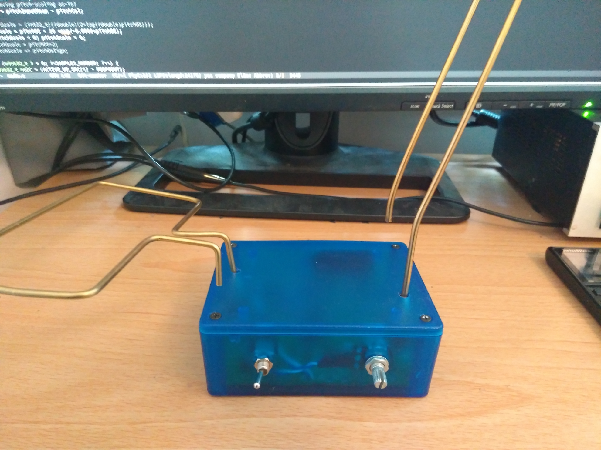
The device uses a pair of 555 timers to translate hand-position to frequency, which is measured by the STM32 and then used to modify a generated sine wave.
The 555 timers operate in the usual astable mode except with the capacitor replaced with an "antenna"; this forms a capacitor between you and the metal whose value varies with the gap between you and the antenna, which then varies the frequency of the 555 output.
The STM32 measures the period of the 555's output wave, calculating the offset from the initial state (calibration is done at power-on); the offset from the calibrated value is used to calculate an amplitude coefficient and a pitch offset. The amplitude coefficient divides a full-scale sine wave which is stored in a lookup table. The pitch offset is used to increase or decrease the time between changes of output value (by adjusting a timer's reload-point), thus stretching or compacting the output wave as required - although with an apparently exponential response, which is partially corrected by the firmware.
The signal is fed into a TDA2822 amplifier in single-ended mode (SE gave better stability on veroboard) with the input amplitude controlled by a potentiometer; the amplifier feeds into either an (optional) internal speaker or headphone jack depending on a SPDT switch.
The hardware is designed in KiCad. If you want to build your own, you're free to use the files so long as you don't try and blame me for anything which goes wrong as a result; it'd be nice to keep my name on the board, too.
The devices are fairly cheap - about £12-15 for the basic device with no LEDs or pitch-adjust potentiometer (which haven't been written in) - I used JLC for the boards and sourced most of the parts from DigiKey.
The cases are drilled by hand, using a 13mm bit for the rear cables, a 6.5mm and 7.5mm bit for the front switch and pot, and a 6mm bit for the (four) holes on the top. There's no drilling template, just use a centre-punch in the right place for the hole's purpose and drill.
The Antennae (capacitor plates, really) are not too critical. Mine are made from thin brass rod which will fit into the jacks; any conductor which fits the jacks will work - make it into a loop which looks like a theremin antenna aught, with one "leg" slightly shorter than the other for the non-connected end. The bigger the antenna the more sensitive the response generally speaking, although I've found that there's not much to gain with this device from a huge antenna.
The firmware uses device files from ST Micro and ARM CMSIS, the rest can be blamed on me. The ST HAL is not being used, because it looked like a good idea to not use it when I started...
The software is fairly simple although does make heavy use of the DMA engine and Timers - these are described in the chip reference manual and, briefly, in comments.
The firmware builds with Make and Arm GCC (I suspect ARMCC6 would work, too, but I'm not going to try it) and should build on most *nix systems - it might work on Windows under WSL or mingw, but you're on your own with that one. For anyone who doesn't want to build the firmware, the latest binary is just in the build directory.
The firmware can be flashed with your favourite flashing tool; a script for an ST-Link V2 with OpenOCD is provided, but I recommend just using STMCubeProg if you're either inexperienced or running Windows.
This was initially designed as a lab kit for the York Engineering Society.
| Qty | Value | Footprint | References |
|---|---|---|---|
| 10 | .1u | Capacitor_THT:C_Rect_L4.0mm_W2.5mm_P2.50mm | C1, C2, C3, C5, C9, C10, C12, C13, C14, C15 |
| 4 | 1Meg | Resistor_THT:R_Axial_DIN0207_L6.3mm_D2.5mm_P10.16mm_Horizontal | R12, R13, R14, R15 |
| 4 | DNF | Resistor_THT:R_Axial_DIN0207_L6.3mm_D2.5mm_P10.16mm_Horizontal | R1, R2, R3, R4 |
| 3 | DNF | LED_THT:LED_D5.0mm | D1, D2, D3 |
| 2 | 100u | Capacitor_THT:CP_Radial_D5.0mm_P2.50mm | C6, C7 |
| 2 | 10k | Resistor_THT:R_Axial_DIN0207_L6.3mm_D2.5mm_P10.16mm_Horizontal | R16, R17 |
| 2 | 1K | Resistor_THT:R_Axial_DIN0207_L6.3mm_D2.5mm_P10.16mm_Horizontal | R10, R11 |
| 2 | Antenna | MountingHole:MountingHole_3.2mm_M3_Pad_Via | ANT1, ANT2 |
| 2 | D | Diode_THT:D_DO-41_SOD81_P10.16mm_Horizontal | D5, D6 |
| 2 | DNF | Button_Switch_THT:SW_PUSH_6mm | SW1, SW2 |
| 2 | Jumper_2_Open | Jumper:SolderJumper-2_P1.3mm_Open_TrianglePad1.0x1.5mm | JP1, JP2 |
| 2 | MountingHole_Pad | MountingHole:MountingHole_3.7mm_Pad | H1, H2 |
| 2 | NE555P | Package_DIP:DIP-8_W7.62mm | U3, U4 |
| 2 | TestPoint | TestPoint:TestPoint_Loop_D2.50mm_Drill1.0mm | TP1, TP2 |
| 1 | 10k | Connector_PinHeader_2.54mm:PinHeader_1x03_P2.54mm_Vertical | RV2 |
| 1 | 1u | Capacitor_THT:C_Rect_L4.0mm_W2.5mm_P2.50mm | C4 |
| 1 | 4.7 | Resistor_THT:R_Axial_DIN0207_L6.3mm_D2.5mm_P10.16mm_Horizontal | R7 |
| 1 | 470u | Capacitor_THT:CP_Radial_D5.0mm_P2.50mm | C8 |
| 1 | 510k | Resistor_THT:R_Axial_DIN0207_L6.3mm_D2.5mm_P10.16mm_Horizontal | R5 |
| 1 | AP2204K-3.0 | Package_TO_SOT_SMD:SOT-23-5 | U1 |
| 1 | AudioJack3_Dual_Switch | Connector_Audio:Jack_3.5mm_CUI_SJ1-3525N_Horizontal | J2 |
| 1 | Conn_01x02_Female | Connector_PinHeader_2.54mm:PinHeader_1x02_P2.54mm_Vertical | J1 |
| 1 | Conn_01x03_Female | Connector_PinHeader_2.54mm:PinHeader_1x03_P2.54mm_Vertical | J4 |
| 1 | Conn_ARM_JTAG_SWD_10 | Connector_PinHeader_1.27mm:PinHeader_2x05_P1.27mm_Vertical | SWD1 |
| 1 | DNF | Connector_PinHeader_2.54mm:PinHeader_1x03_P2.54mm_Vertical | RV1 |
| 1 | DNF | Capacitor_THT:C_Rect_L4.0mm_W2.5mm_P2.50mm | C16 |
| 1 | D_Zener 12V | Diode_THT:D_DO-41_SOD81_P10.16mm_Horizontal | D4 |
| 1 | STM32G051K8T6 | Package_QFP:LQFP-32_7x7mm_P0.8mm | U5 |
| 1 | SW_SPDT | Connector_PinHeader_2.54mm:PinHeader_1x03_P2.54mm_Vertical | SW3 |
| 1 | Speaker | Connector_PinHeader_2.54mm:PinHeader_1x02_P2.54mm_Vertical | SP1 |
| 1 | TDA2822 | Package_SO:SOIC-8_3.9x4.9mm_P1.27mm | U2 |
| 1 | USB_B_Micro | Connector_USB:USB_Micro-B_Amphenol_10104110_Horizontal | J3 |


GadgetReboot/ESP32-A1S
Breakout PCB for the ESP32-A1S module including an audio amp and basic GPIO headers, USB interface

ksmola/PriusG2
Inverter control board for Toyota Prius Gen 2 (XW20) inverter. Some of the schematics are based on Johannes Huebner's work found here. Running openinverter firmware.

zartarn15/hubble-metal-detector
STM32-based digital metal detector with custom hardware and embedded DSP firmware.

doobedoobedo/Huebner_Inverter
KiCAD port of https://github.com/jsphuebner/inverter-hardware mainboard V1.2

OpenRetroHQ/sega-gamegear-audio-original
Sega Game Gear Audio Original - Remake of the original TDA2882M audio board for the game gear


SL-RU/simple_headphones_dac
Simple board with DAC cs4335 and amplifier TDA2822
It measures 100 × 63 mm and has 2 copper layers, 1.6 mm thick.
59 parts, built around the STM32G051K8T6, TDA2822D and NE555P. The full list of its parts is on this page, with links to each part's symbol and footprint where PCBKit's library has them.
From the super-cow-powers/ThereMin repository on GitHub, at the commit this page was made from: the board is PCB/Digital Theremin.kicad_pcb and its schematic PCB/Digital Theremin.kicad_sch. PCBKit opens the board in the browser, with nothing to install.
Its repository states no licence, so its author keeps all rights: ask super-cow-powers before reusing the design.