4 layers93.7 × 43.7 mm
Flight Computer
SunDevilRocketry/Flight-Computer
General purpose flight computer for high powered rocketry projects.
113 parts5

 SunDevilRocketry/Liquid-Engine-Controller1
Main microcontroller board for embedded control of SDR's liquid bipropellant engine.
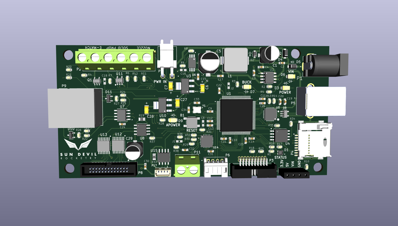
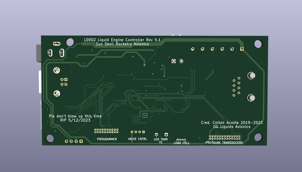
Engine Controller is an open-source printed circuit board by SunDevilRocketry, from the SunDevilRocketry/Liquid-Engine-Controller repository on GitHub. It is a 4-layer board of 116.8 × 56.7 mm with 119 parts on 180 nets, routed with 1,387 tracks and 177 vias.
It is built around the CP2102-GMR, AD623ARZ-R7 and SST25VF040B-50-4I-S2AE-T, with the MAX4617EUE+T, TS391IYLT and SML-LX1206GC-TR among its other parts. Its parts include 38 resistors, 33 capacitors, 14 ICs, 14 connectors and 11 diodes. It belongs with the STM32 boards of this library.


Current PCB Revision: 5.1
PCB Part Number: L0002
The Liquid Engine Controller is the main embedded processor of Sun Devil Rocketry's Liquid Engine. As the brains of the engine, the controller is responsible for executing propellant feed sequences semi-autonomously, logging sensor data, and transmitting engine telemetry. The controller is equipped with an STM32 ARM Cortex M7 processor and 4Mb of external flash for data logging. The board includes a micro-SD card jack for easy access to the logged data. The board includes many power sources for flexible use of the controller during testing and normal operation. These include a 12V power jack, a USB Type B connector, and a 2-pin male pin header. The board includes short circuit protection on the main power rail and regulates the multiplexed supply to 5V and 3.3V with a buck converter and linear regulator (LDO) respectively. The board interfaces with a PC through either the USB port or the 8-pin telemetry connector, which allows wireless transceiver modules with either a UART or SPI interface to be connected. The screw terminals on the board connect to the ignition circuitry. An e-match is used to initiate combustion, and two continuity wires are used to provide the controller feedback on the ignition state. The ignition current is routed through an additional screw terminal which serves as a safety/arming switch. The board interfaces with all of the engine sensors, including eight pressure transducers, a thermocouple, and a load cell. The pressure transducer outputs are amplified with a programmable-gain instrumentation amplifier, which allows for up to 256 calibration settings. The thermocouple output is processed using a cold-junction compensation IC. Additionally, the board includes a reset button and several LEDs for visual indication of power and firmware status.
Working Directory Structure:
cad: 3d models
doc: documentation
img: images of circuit/footprints for github display
lib: libraries for schematic symbols and footprints
production: files needed for pcb fabrication, e.g. gerbers, profile, drill file
sim: simulation models/files
src: source design files, e.g. schematic and PCB layout files
| Qty | Value | Footprint | References |
|---|---|---|---|
| 13 | 0.1uF | Engine-Controller:CAP_0603 | C8, C9, C11, C13, C14, C15, C16, C20, C21, C22, C24, C31, C32 |
| 11 | 10k | Engine-Controller:RES_0603 | R6, R8, R10, R11, R12, R14, R20, R34, R35, R36, R37 |
| 6 | 1uF | Engine-Controller:CAP_0603 | C2, C3, C12, C18, C19, C30 |
| 4 | 10 | Engine-Controller:RES_0603 | R22, R23, R24, R25 |
| 4 | 100k | Engine-Controller:RES_0603 | R4, R7, R15, R18 |
| 4 | 10uF | Engine-Controller:T491A106K010AT | C6, C7, C27, C28 |
| 4 | Mounting-Hole | Engine-Controller:MountingHole_4.3mm_M4_DIN965 | H1, H4, H5, H6 |
| 4 | SML-LX1206GC-TR | Engine-Controller:SML-LX1206GC-TR | D3, D6, D7, D9 |
| 3 | 2.2uF | Engine-Controller:CAP_0603 | C17, C23, C26 |
| 3 | 2k | Engine-Controller:RES_0603 | R2, R31, R32 |
| 2 | 100 | Engine-Controller:RES_0603 | R26, R27 |
| 2 | 240 | Engine-Controller:RES_0603 | R5, R28 |
| 2 | 2M | Engine-Controller:RES_0603 | R30, R38 |
| 2 | 470 | Engine-Controller:RES_0603 | R3, R9 |
| 2 | 68uF | Engine-Controller:EEEFPV680XAP | C1, C29 |
| 2 | 82 | Engine-Controller:RES_0603 | R1, R16 |
| 2 | 8pF | Engine-Controller:CAP_0603 | C33, C34 |
| 2 | AD623ARZ-R7 | Engine-Controller:AD623ARZ-R7 | U8, U15 |
| 2 | Jumper_NO | Engine-Controller:Jumper-NO | J1, J2 |
| 2 | LMS8117AMP-3.3_NOPB | Engine-Controller:LMS8117AMP-3.3NOPB | U3, U10 |
| 2 | MAX4617EUE+T | Engine-Controller:max4617eue | U12, U13 |
| 2 | SM5819PL-TP | Engine-Controller:SM5819PL-TP | D4, D5 |
| 2 | SMBJ36CA-13-F | Engine-Controller:CDSOT23-SM712 | D10, D11 |
| 1 | 0530470410 | Engine-Controller:0530470410 | P17 |
| 1 | 10nF | Engine-Controller:CAP_0603 | C4 |
| 1 | 140-504-415-000 | Engine-Controller:140-504-415-000 | P6 |
| 1 | 150uF | Engine-Controller:EEEFP1E151AL | C5 |
| 1 | 1M | Engine-Controller:RES_0603 | R29 |
| 1 | 20021511-00026T4LF | Engine-Controller:20021511-00026T4LF | P8 |
| 1 | 20k | Engine-Controller:RES_0603 | R21 |
| 1 | 280 | Engine-Controller:RES_0603 | R17 |
| 1 | 282837-2 | Engine-Controller:282837-2 | P11 |
| 1 | 282837-6 | Engine-Controller:282837-6 | P2 |
| 1 | 3.3k | Engine-Controller:RES_0805 | R19 |
| 1 | 3220-20-0200-00 | Engine-Controller:3220-20-0200-00 | P3 |
| 1 | 33uH | Engine-Controller:SRP1038A-330M | L1 |
| 1 | 4.7k | Engine-Controller:RES_0603 | R13 |
| 1 | 4.7uF | Engine-Controller:CAP_0603 | C10 |
| 1 | 470 | Engine-Controller:RES_0805 | R33 |
| 1 | 54602-908LF | Engine-Controller:54602-908LF | P9 |
| 1 | 647676-2 | Engine-Controller:647676-2 | P7 |
| 1 | CLMVC-FKA-CL1D1L71BB7C3C3 | Engine-Controller:CLMVC-FKA-CL1D1L71BB7C3C3 | D1 |
| 1 | CP2102-GMR(QFN28) | Engine-Controller:CP2012-GMR | U5 |
| 1 | ECS-240-18-33-JGN-TR | Engine-Controller:ECS-240-18-33-JGN-TR | Y1 |
| 1 | EJ508A | Engine-Controller:12V_power_jack | P1 |
| 1 | LM22672MRE-5.0_NOPB | Engine-Controller:LM22672MRE-5.0_NOPB | U2 |
| 1 | Logo | Engine-Controller:Logo | LOGO2 |
| 1 | Micro_SD_Card | Engine-Controller:MEM2075-00-140-01-A | P4 |
| 1 | PPTC041LFBN-RC | Engine-Controller:PPTC041LFBN-RC | P18 |
| 1 | PTS647SM38SMTR2LFS | Engine-Controller:PTS647SM38SMTR2LFS | B1 |
| 1 | QFN65P500X500X100-21N_MCP96RL00T-E/MX | Engine-Controller:MCP96L01T-E_MX | U14 |
| 1 | QS5U17TR | Engine-Controller:QS5U17TR | Q1 |
| 1 | RB160VAM-60TR | Engine-Controller:RB160VAM-60TR | D2 |
| 1 | SN65HVD71DR | Engine-Controller:SN65HVD71DR | U7 |
| 1 | SP0504BAHTG | Engine-Controller:SP0504BAHTG | D8 |
| 1 | SST25VF040B-50-4I-S2AE-T | Engine-Controller:SST25VF040B-50-4I-S2AE-T | U4 |
| 1 | STM32H750VBTx | Engine-Controller:STM32H750VBT6 | U1 |
| 1 | TPS2115APWR | Engine-Controller:TPS2115APWR | U6 |
| 1 | TS391IYLT | Engine-Controller:TS391IYLT | U11 |
| 1 | USB | Engine-Controller:USB-TypeB | P5 |
It measures 116.8 × 56.7 mm and has 4 copper layers, 1.6 mm thick.
119 parts, built around the CP2102-GMR, AD623ARZ-R7, SST25VF040B-50-4I-S2AE-T and MAX4617EUE+T. The full list of its parts is on this page, with links to each part's symbol and footprint where PCBKit's library has them.
From the SunDevilRocketry/Liquid-Engine-Controller repository on GitHub, at the commit this page was made from: the board is src/Engine-Controller/Engine-Controller.kicad_pcb and its schematic src/Engine-Controller/Connectors.kicad_sch. PCBKit opens the board in the browser, with nothing to install.
Its repository states no licence, so its author keeps all rights: ask SunDevilRocketry before reusing the design.
SunDevilRocketry/Flight-Computer
General purpose flight computer for high powered rocketry projects.

cacost12/SDR-Flight-Computer-Lite-PCB
Current PCB Revision: 1.0 PCB Part Number: A0007

cacost12/SDR-Liquid-Engine-Controller-PCB
Current PCB Revision: 4.0 PCB Part Number: L0002

cacost12/SDR-Ground-Station-Telemetry-PCB
Current PCB Revision: 1.0 PCB Part Number: A0005

SunDevilRocketry/Wheatstone-Bridge
Pressure transducer signal emulation board to facilitate electronics testing

cacost12/SDR-Instrumentation-Amplifier-PCB
Rail to Rail Instrumentation Amplifier with Regulated Supply

SunDevilRocketry/5V-Power-Supply
The 5V power supply is a DC-DC switching power supply prototype board for testing the A0002 power supply.

xwlred/OpenHD-CM4-Carrier-Board
[Shelved] RPI CM4 carrier for use in OpenHD