Skip to the content
PCBKitNew board
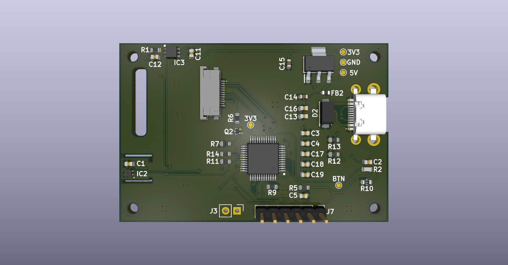
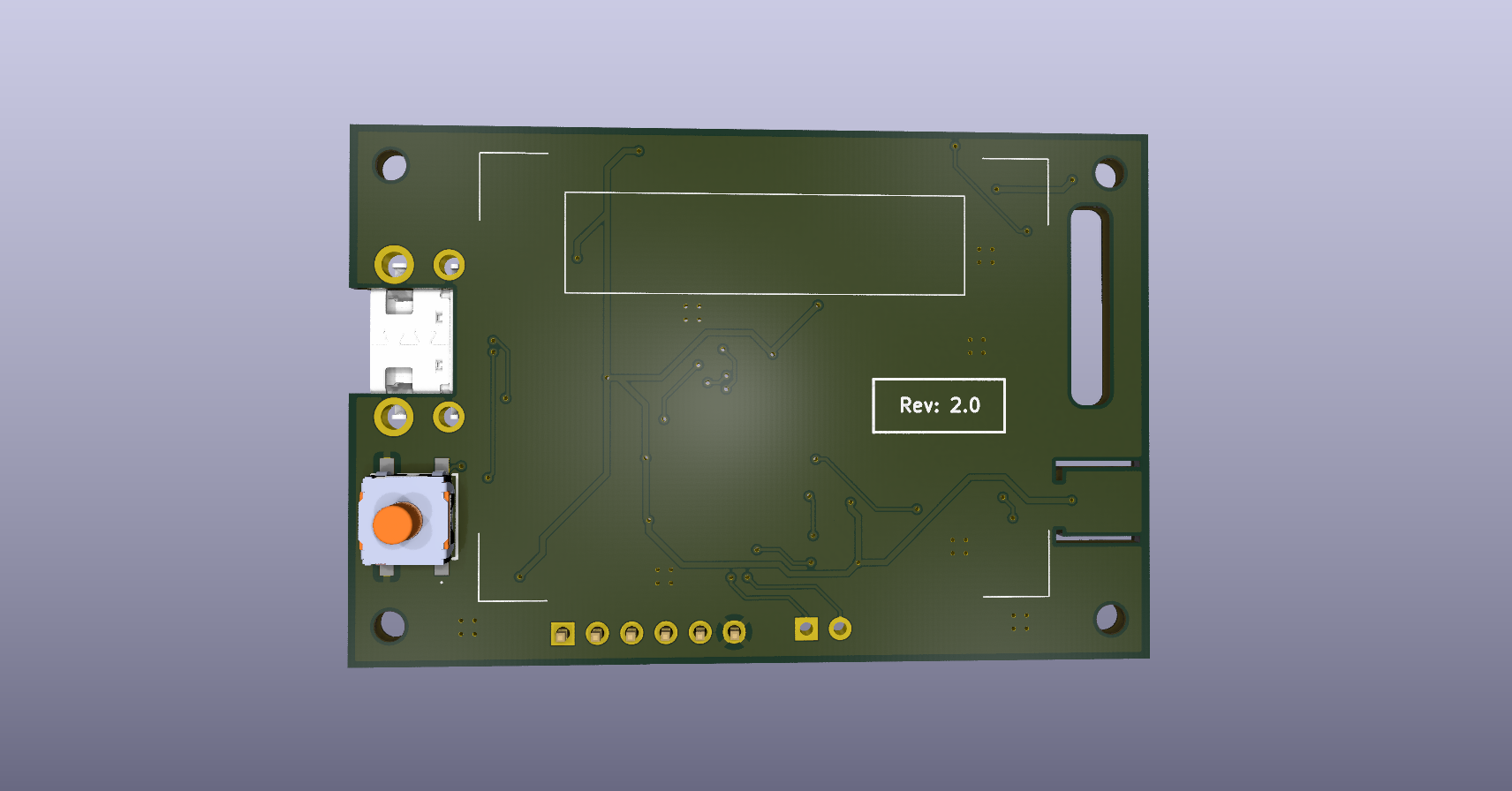
2 layers60 × 40 mmAMUN, the printed circuit board in 3D

Open source hardware to monitor temperature, humidity and VOC in an indoor environment

Size
60 × 40 mm
Copper layers
2
Thickness
1.6 mm
Parts
47
Nets
61
Pads
175
Tracks, vias
337, 64
Pours
2
Routed
Yes
KiCad
KiCad 10.0 (file 20260206)
Created
23 Sep 2026
Updated
18 Oct 2026

Overview

AMUN is an open-source printed circuit board by Summanuss, from the Summanuss/openairqmonitor repository on GitHub, published under the Apache-2.0 licence. It is a 2-layer board of 60 × 40 mm with 47 parts on 61 nets, routed with 337 tracks and 64 vias.

It is built around the STM32L431CCT6TR, SGP40-D-R4 and SHT40-AD1B-R2, with the AZ1117CH-3.3TRG1, SFV12R-1STBE1HLF and SSM3K16FV,L3F among its other parts. Its parts include 14 capacitors, 11 resistors, 5 ICs, 4 connectors and 1 diode. It belongs with the STM32 boards of this library.

Main components

6

README

README.md

Open AirQ Monitor

License Status Hardware Rev

PCB Back PCB Front

Table of Contents

Overview

  • Description: STM32 based custom-board to monitor temperature, humidity and VOC
  • Status: Stable - Revision 2.0
  • License: Apache-2.0 license

Description

Open AirQ Monitor is a very simple STM32 custom PCB with a temperature/humidity sensor and a VOC sensor. It's goal is to be a consumer / gadget product which you can keep in your bedroom, rather than a professional industrial solution to monitor ambient parameters. Given that, I decided to use an LCD TFT RGB display so the firmware application can be more "fancy" and "nice".
As an hobbistic project, I wanted it to be as cheap and easy to design as possible.
This can be seen as a starting point to build a more advanced product with more functionality, so feel free to fork the repo and customize it as you like!

Key Features

  • LCD TFT [128x160 px] Display
  • Dimmable display backlight
  • USB-C powered (5V)
  • Push-button as a general input or EXTI
  • Real-time temperature and humidity measurement
  • Real-time VOC measurement

Technical Specifications

ParameterValue
Input Voltage5V
Typical Current DrawTODO (e.g. ~xx mA idle / xx mA peak)
Microcontroller / CoreSTM32L431CCT6TR
Microcontroller / RAM64 KB
Microcontroller / FLASH256 KB
VOC SensorSGP40-D-R4
Temp/Humidity SensorSHT40-AD1B-R2
TFT DisplayER-TFT018-3
Dimensions60x40 mm
Mounting HolesM2

Project Structure

text
├── docs/             # Documentation, schematics PDF, and renders
├── fabrication/      # Production files (Gerbers, BOM, Pick & Place)
├── design/           # KiCad project source files
├── exported          # .step, BOM, ...
├── LICENSE           # License file
└── README.md         # Project documentation

Hardware Documentation

Check the docs/ folder.

Pinout & Connectors

For the complete pinout check the schematic.

PinFunctionDescriptionDirection
PA1SPI_CLKSPI Clock SignalOut
PA3BUTTON_INExternal Button SignalIn
PA4DC_DISPLAYData / Command Display SignalOut
PA5RST_DISPLAYDisplay Reset SignalOut
PA6CS_DISPLAYDisplay Chip Select SignalOut
PA7SPI_MOSIDisplay Serial Data SignalOut
PA8BCK_LIGHT_DISPLAYDisplay Backlight SignalOut
PA9I2C_SCLSCL Line of I2C busOut
PA10I2C_SDASDA Line of I2C busIn / Out
PA11SWDIOSerial Wire Data SignalIn / Out
PA14SWCLKSerial Wire Protocol Clock SignalIn
PB3SWOSerial Wire Protocol Output SignalOut

Getting Started

Opening the KiCad project

  1. Install KiCad 10.0 or later.
  2. Clone this repository.
  3. Custom symbol files should be automatically embedded (KiCad versione > 6). If this is not the case, open an issue an I'll fix it ASAP.

Generating fabrication files

  1. Open the PCB editor in KiCad.
  2. Export Gerbers, drill files, and Pick & Place using KiCad's built-in plotter (or the AISLER plugin, see Ordering & Fabrication Guidelines).
  3. Upload the generated files in your chosen manufacturer website (es. AISLER)
  4. Check the correctness of the layout in the preview before ordering!

Flashing the firmware

  1. Connect an SWD programmer (e.g. ST-Link V2/V3) to the SWDIO/SWCLK/SWO pins.
  2. Build and flash the firmware from the Test Firmware repository following its own instructions.
  3. Power the board via USB-C (5V) once flashing is complete.

Ordering & Fabrication Guidelines

The chosen manufacturer is AISLER and every constraints in the layout that I used is based on their specifications.
I used the AISLER plugin for KiCad to export all fabrication files. Just for reference, I created them manually in fabrication directory.
However, I didn't double checked those and a further analysis is suggested. Also, the PCB was manually assembled by me and no assembly services were used from the manufacturer.

Test Firmware

Test firmware written in C is provided here
More information about it are provided in the linked repository.

Known Issues & Future Improvements

  • The SHT40 sensor is not perfectly thermally decoupled from the PCB and its reading can be a bit altered from the heat generated from the display and the rest of the PCB.
  • The flashing and debugging pins are permanently soldered on the PCB which is not optimal.
    Ideas for revision 3.0:
  • Correct the known issues.
  • Provide the support for a battery powered device.

Safety Notes

  • The board is powered via USB-C at 5V - use a standard certified USB-C cable/power source.
  • Use the SWD connector interface ONLY for flashing and debug.

Revision History

  • v2.0: Final and stable version
  • v1.0: First working prototype

License

Distributed under the Apache-2.0 License. See LICENSE for more information.

Acknowledgments

I would like to thanks my friends which worked on the final firmware product and device enclouse:

  • D.G.
  • A.B.

Contact

Mail: serafin.jacopo99@gmail.com

Parts

47
QtyValueFootprintReferences
8100nFamun_lib:CAPC1608X90NC1, C2, C3, C4, C5, C17, C18, C19
510Kamun_lib:RESC1608X55NR5, R7, R9, R11, R14
4MountingHoleMountingHole:MountingHole_2.2mm_M2_DIN965H1, H2, H3, H4
21uFamun_lib:CAPC1608X90NC11, C12
22.2uFamun_lib:CAPC1608X90NC13, C16
23V3TestPoint:TestPoint_Pad_D1.0mm3V3, 3V3
25.1Kamun_lib:RESC1608X55NR12, R13
110amun_lib:RESC1608X55NR6
1100amun_lib:RESC1608X60NR10
110uFamun_lib:GRM18xC14
122uFamun_lib:GRM18xC15
14.7Kamun_lib:RESC1608X50NR2
15VTestPoint:TestPoint_Pad_D1.0mm5V
1AZ1117CH-3.3TRG1amun_lib:SOT230P700X180-4NIC4
1BLM18PG330SH1Damun_lib:BLM18SP221SN1BFB2
1BTNTestPoint:TestPoint_Pad_D1.0mmBTN
1Conn_01x02_PinConnector_PinHeader_2.54mm:PinHeader_1x02_P2.54mm_VerticalJ3
1Conn_01x06Connector_PinHeader_2.54mm:PinHeader_1x06_P2.54mm_VerticalJ7
1EL2_52_35J_LFSamun_lib:EL25235JLFSS1
1ER-TFT018-3amun_lib:ER-TFT018-3U2
1GNDTestPoint:TestPoint_Pad_D1.0mmGND
1RC0603FR-134R7Lamun_lib:RESC1608X55NR1
1SFV12R-1STBE1HLFamun_lib:SFV12R1STBE1HLFJ6
1SGP40-D-R4amun_lib:SON80P244X244X95-7NIC3
1SHT40-AD1B-R2amun_lib:SHT40AD1BR2IC2
1SMAJ6.5CA_TR7amun_lib:DIOM5127X250ND2
1SSM3K16FV,L3Famun_lib:VESM_SOT-723_Q2
1STM32L431CCT6TRamun_lib:QFP50P900X900X160-48NIC5
1UJ20-C-H-G-MSMT-4B-P16-TRamun_lib:UJ20CHGMSMT4BP16TRJ1

Questions

How big is the AMUN PCB?

It measures 60 × 40 mm and has 2 copper layers, 1.6 mm thick.

What parts does the AMUN use?

47 parts, built around the STM32L431CCT6TR, SGP40-D-R4, SHT40-AD1B-R2 and AZ1117CH-3.3TRG1. The full list of its parts is on this page, with links to each part's symbol and footprint where PCBKit's library has them.

Where can I download the AMUN KiCad files?

From the Summanuss/openairqmonitor repository on GitHub, at the commit this page was made from: the board is design/AMUN.kicad_pcb and its schematic design/AMUN.kicad_sch. PCBKit opens the board in the browser, with nothing to install.

Can I use the AMUN design in my own project?

Its repository publishes it under the Apache-2.0 licence: you may reuse it on that licence's terms (keep the author's notice, and for a copyleft licence share your changes alike).

Similar boards

  • 4 layers47.1 × 45.3 mmMixed signal Board Rev D, the printed circuit board in 3D

    Mixed signal Board Rev D

    Akhilesh-design-02/STM32F407-Hardware-Design

    4-layer STM32F407 mixed-signal PCB design featuring I2C/I2S/USB interfaces, SGP40 & SHT40 sensors, power plane splits, and star grounding for noise isolation.

    92 parts
  • 4 layers112 × 100 mmAi05-env sensors, the printed circuit board in 3D

    Ai05-env sensors

    leafony/ai05-env-sensors

    全センサーは Leafony Bus の 3.3 V・I²C に接続します。基板は 23 × 20 mm、4層、板厚 0.8 mm です。

    252 parts
  • 2 layers60 × 40 mmCanary, the printed circuit board in 3D

    Canary

    offgridevices/offgrid-hardware

    Open hardware from OffGrid Devices. One folder per board. CERN-OHL-S.

    52 partsCERN-OHL-S-2.0
  • 2 layers25.1 × 25.2 mmMini Environmental Sensor, the printed circuit board in 3D

    Mini Environmental Sensor

    MbFredys/PCB-Mini-Environmental-Sensor

    Compact ESP32-C3 environmental-sensor PCB design using BME280 and SGP40 for temperature, humidity, pressure, and VOC-based air-quality sensing.

    34 parts14
  • 4 layers95 × 67 mmLoRaDongle iCE40, the printed circuit board in 3D

    LoRaDongle iCE40

    marrrk/LoRaDongle

    A Risc-V Based LoRa custom PCB

    145 parts4
  • 2 layers44.7 × 93.6 mmUltisense, the printed circuit board in 3D

    Ultisense

    darshg321/Ultisense

    an esp32-s3 devboard made to sense as many things as possible

    94 parts3
  • 4 layers74 × 56 mmAtmos, the printed circuit board in 3D

    Atmos

    HearnChristian/atmos-sense

    ESP32-based atmospheric sensing node: BME280 environmental sensing and AS3935 lightning detection over I2C, designed for drone integration. KiCad hardware plus firmware.

    73 parts1MIT
  • 4 layers50.8 × 22.9 mmWeather Feather Wing, the printed circuit board in 3D

    Weather Feather Wing

    benjamincrockett/Weather-Feather-Wing

    A circuit board incorporating temperature, humidity, atmospheric pressure, and CO2 sensors into an Adafruit Feather Wing form factor with Stemma QT connectors.

    35 parts