
2 layers56 × 91 mm
Burstcart
ytmytm/plus4-burstcart
Burst (fast serial) capable cartridge for Commodore C16/116/Plus4
21 parts4

 SukkoPera/ReSeed15
Sounds from C64 now for Plus/4!
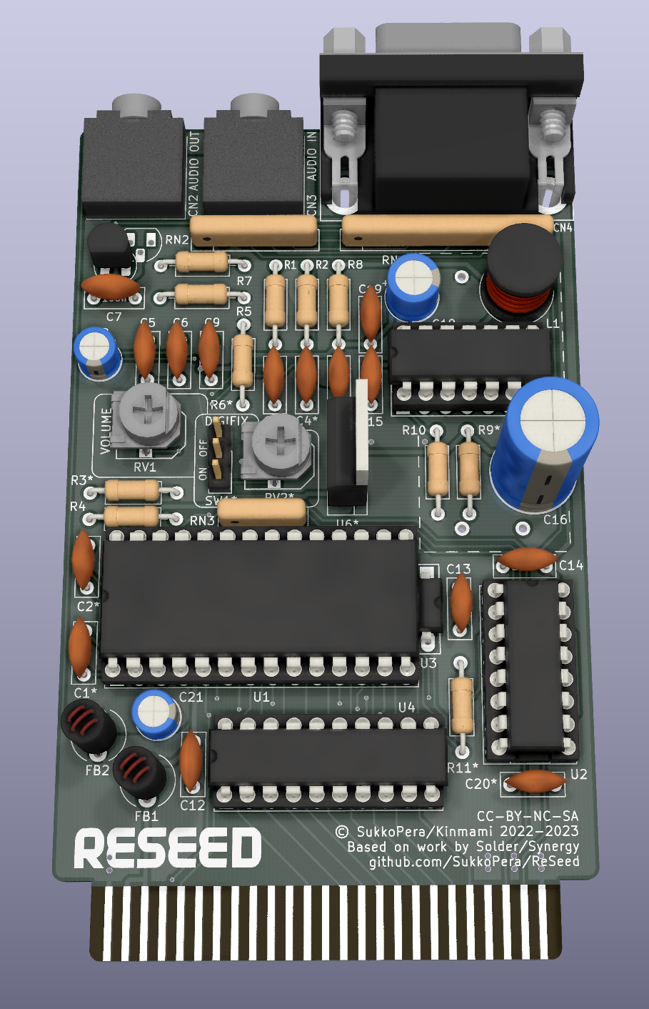
ReSeed is an open-source printed circuit board by SukkoPera, from the SukkoPera/ReSeed repository on GitHub. It is a 2-layer board of 60.8 × 99.9 mm with 59 parts on 106 nets, routed with 696 tracks and 43 vias.
It is built around the 74HCT245, TL497ACNS and CD74HCT4520E, with the LM7809T, 28C0236-0EW-10 and 2SC1815 among its other parts. Its parts include 21 capacitors, 11 resistors, 7 ICs, 4 connectors and 2 transistors. It belongs with the retro computing and games and audio and music boards and the FPGA and CPLD boards of this library.




ReSeed is an expansion card for the Commodore 16 and Plus/4 computers that allows interfacing the computer with a MOS 6581 or 8580 Sound Interface Device, the chip that is used to deliver audio on the Commodore 64.
It is based on a design by Solder of Synergy.
Sounds from the C64 now for the Plus/4! Just plug the card into the Expansion Port! You can adjust the volume on the card. You can hear the sound over the Plus/4 audio or take it over a 3.5mm-Stereo-Cinch to a mixer or HiFi-Device. A 9-pin D-SUB connector allows connecting a 3rd (analog!) joystick or a proportional-mouse or (why not?) paddles!
(Slight rewording of Solder's original description of the card.)
ReSeed is derived from Solder's SIDcard, with a few enhancements.
The focus for V2 was on reducing the output noise.
If you want to assemble a card, please read the assembly notes on the Wiki carefully or you might destroy your SID chip!
Most SID replacements will not work correctly. This is because for technical reasons the clock that is provided to the SID has a lower frequency than what it gets on the C64 (~886 vs ~985 kHz). Most SID replacements do not use this clock signal at all and just assume C64 frequency (I guess), leading to incorrect data transfers. This is the case for the SwinSID firmware, for instance. See below for a table of tested SID replacement devices.
| SID Device | Compatibility | Source | Notes |
|---|---|---|---|
| ARMSID | Yes | Root42 | May have subtle incompatibility (detected during porting of config tool to +4), but unlikely to be seen in practise. |
| SIDKick | In Progress | SIDKick Pico Github | |
| SwinSID | No | SukkoPera | One report of compatibility, but no evidence provided. |
| BackSID | No | BackBit Forums | Discontinued closed-source product; firmware unlikely to be patched. |
| KungFuSID | No | SukkoPera | |
| PD-SID | No | SteveGuidi | Firmware v191; no sound output and USB port inhibits proper seating in socket (obstructed by socketed CD74HCT4520E). |
You can get images of the disks Solder used to ship with his SIDcard here. These will help making sure that the card works as intended.
Here is also a list of a lot of C16/+4 games and software supporting the card.
If you want to get this board produced, you are recommended to get the latest release rather than the current git version, as the latter might be under development and is not guaranteed to be working.
Every release is accompanied by its Bill Of Materials (BOM) file and any relevant notes about it, which you are recommended to read carefully.
A 3D-printable enclosure is currently available for this board, it was kindly contributed by Starquake and it is available in the enclosure folder.
Usage should be self-explanatory, just note that there are two slightly different versions depending on the SID model, as the one for the 8580 has an extra hole in the upper shell for the Digifix). You will probably have to bend the ferrites and capacitor at the bottom of the board a little to the side.
2x countersunk head screws M3x5mm will be required for assembly.
Please see this thread on Forum64 for more information and printing recommendations.
SteveGuidi kindly contributed original-264-style labels for the completed cartridge.
The ReSeed documentation, including the design itself, is copyright © SukkoPera 2022-2023 and is licensed under the Creative Commons Attribution-NonCommercial-ShareAlike 4.0 International License.
This documentation is distributed as is and WITHOUT ANY EXPRESS OR IMPLIED WARRANTIES whatsoever with respect to its functionality, operability or use, including, without limitation, any implied warranties OF MERCHANTABILITY, SATISFACTORY QUALITY, FITNESS FOR A PARTICULAR PURPOSE or infringement. We expressly disclaim any liability whatsoever for any direct, indirect, consequential, incidental or special damages, including, without limitation, lost revenues, lost profits, losses resulting from business interruption or loss of data, regardless of the form of action or legal theory under which the liability may be asserted, even if advised of the possibility or likelihood of such damages.
If you want to get some boards manufactured, you can get them from PCBWay through this link:

You get my gratitude and cheap, professionally-made and good quality PCBs, I get some credit that will help with this and other projects. You won't even have to worry about the various PCB options, it's all pre-configured for you!
Also, if you still have to register, you can use this link to get some bonus initial credit (and yield me some more).
You can also buy me a coffee if you want:

| Qty | Value | Footprint | References |
|---|---|---|---|
| 9 | 100n | Capacitor_THT:C_Disc_D7.0mm_W2.5mm_P5.00mm | C7, C9, C10, C11, C12, C13, C14, C17, C19 |
| 3 | 100 | Resistor_THT:R_Axial_DIN0207_L6.3mm_D2.5mm_P10.16mm_Horizontal | R1, R2, R11 |
| 2 | 10u | Capacitor_THT:CP_Radial_D5.0mm_P2.00mm | C8, C21 |
| 2 | 1k | Resistor_THT:R_Axial_DIN0207_L6.3mm_D2.5mm_P10.16mm_Horizontal | R3, R5 |
| 2 | 2.2n | Capacitor_THT:C_Disc_D7.0mm_W2.5mm_P5.00mm | C3, C4 |
| 2 | 22n | Capacitor_THT:C_Disc_D7.0mm_W2.5mm_P5.00mm | C1, C2 |
| 2 | 28C0236-0EW-10 | Inductor_THT:L_Radial_D6.0mm_P4.00mm | FB1, FB2 |
| 2 | 470p | Capacitor_THT:C_Disc_D7.0mm_W2.5mm_P5.00mm | C6, C20 |
| 1 | 1.2k 1% | Resistor_THT:R_Axial_DIN0207_L6.3mm_D2.5mm_P10.16mm_Horizontal | R10 |
| 1 | 100 | Resistor_THT:R_Array_SIP10 | RN1 |
| 1 | 1000u/25V | Capacitor_THT:CP_Radial_D10.0mm_P5.00mm | C16 |
| 1 | 100k | Resistor_THT:R_Axial_DIN0207_L6.3mm_D2.5mm_P10.16mm_Horizontal | R7 |
| 1 | 100p | Capacitor_THT:C_Disc_D7.0mm_W2.5mm_P5.00mm | C15 |
| 1 | 100u | Inductor_THT:L_Radial_D8.7mm_P5.00mm_Fastron_07HCP | L1 |
| 1 | 100u/16V | Capacitor_THT:CP_Radial_D6.3mm_P2.50mm | C18 |
| 1 | 10k | ReSeed:Pot_Bourns_3306P | RV1 |
| 1 | 10k | Resistor_THT:R_Array_SIP4 | RN3 |
| 1 | 10k | Resistor_THT:R_Axial_DIN0207_L6.3mm_D2.5mm_P10.16mm_Horizontal | R4 |
| 1 | 12.7k 1% | Resistor_THT:R_Axial_DIN0207_L6.3mm_D2.5mm_P10.16mm_Horizontal | R9 |
| 1 | 180k | Resistor_THT:R_Axial_DIN0207_L6.3mm_D2.5mm_P10.16mm_Horizontal | R6 |
| 1 | 1M | ReSeed:Pot_Bourns_3306P | RV2 |
| 1 | 1n | Capacitor_THT:C_Disc_D7.0mm_W2.5mm_P5.00mm | C5 |
| 1 | 2SC1815 | Package_TO_SOT_THT:TO-92_HandSolder | Q101 |
| 1 | 3.3 1%/0.5W | Resistor_THT:R_Axial_DIN0207_L6.3mm_D2.5mm_P10.16mm_Horizontal | R8 |
| 1 | 4.7k | Resistor_THT:R_Array_SIP6 | RN2 |
| 1 | 74HCT245 | Package_DIP:DIP-20_W7.62mm_Socket_LongPads | U3 |
| 1 | AUDIO_IN | ReSeed:AudioJack_SJ1-3525N | CN3 |
| 1 | AUDIO_OUT | ReSeed:AudioJack_SJ1-3525N | CN2 |
| 1 | BC549C | Package_TO_SOT_THT:TO-92_HandSolder | Q1 |
| 1 | CD74HCT4520E | Package_DIP:DIP-16_W7.62mm_Socket_LongPads | U2 |
| 1 | DB9_MALE | ReSeed:DB_9M | CN4 |
| 1 | EDGE_CONNECTOR | ReSeed:C16_Cart_Conn | CN1 |
| 1 | GAL16V8 | Package_DIP:DIP-20_W7.62mm_Socket_LongPads | U4 |
| 1 | JMP_CNT_RST | Jumper:SolderJumper-3_P1.3mm_Open_RoundedPad1.0x1.5mm | JP2 |
| 1 | JMP_GND_LIFT | Jumper:SolderJumper-2_P1.3mm_Bridged_RoundedPad1.0x1.5mm | JP1 |
| 1 | JMP_REG_BYPASS | Jumper:SolderJumper-2_P1.3mm_Open_RoundedPad1.0x1.5mm | JP3 |
| 1 | LICENSE | ReSeed:cc_by_nc_sa | V1 |
| 1 | LM7809 | ReSeed:TO-220-3_Vertical_Round | U6 |
| 1 | LOGO | ReSeed:Logo | V0 |
| 1 | MOS_8580 | Package_DIP:DIP-28_W15.24mm_Socket_LongPads | U1 |
| 1 | STEPUP_MT3608 | ReSeed:ChineseUpstepperMT3608Style | U105 |
| 1 | SW_DIGIFIX | Connector_PinHeader_2.54mm:PinHeader_1x03_P2.54mm_Vertical | SW1 |
| 1 | TL497ACN | Package_DIP:DIP-14_W7.62mm_Socket_LongPads | U5 |
It measures 60.8 × 99.9 mm and has 2 copper layers, 1.6 mm thick.
59 parts, built around the 74HCT245, TL497ACNS, CD74HCT4520E and LM7809T. The full list of its parts is on this page, with links to each part's symbol and footprint where PCBKit's library has them.
From the SukkoPera/ReSeed repository on GitHub, at the commit this page was made from: the board is ReSeed.kicad_pcb. PCBKit opens the board in the browser, with nothing to install.
Its repository states no licence, so its author keeps all rights: ask SukkoPera before reusing the design.
ytmytm/plus4-burstcart
Burst (fast serial) capable cartridge for Commodore C16/116/Plus4


UTS-500-Series/Compressor
A 35 × 110 mm board that sits flat behind the faceplate and carries everything on the panel: the five pots, the four toggles, and both LED meters with their two LM3914 drivers.


loscorpione/VFO-BFO-HF-ESP32-Si5351
VFO & BFO con Si 5351 gestito da ESP32 devkit V1 per la gamma di frequenze HF, da 1 a 30 MHZ

bc-kim/PCB_KiCAD
Tips Footprint of the resisotor and capacitor should be assigned aforetime because assigning those are comfusing when lots of reisistor and capacitors are used. 3. Reference: https://wikidocs.net/103412

carmisergio/denon-preout-mod
PCB designs and firmware for the Denon AVR-X1300W Pre-out mod
