Skip to the content
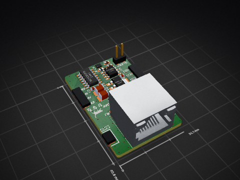
2 layers102.4 × 43 mmTemp sense redesign, the printed circuit board in 3D

Temp sense redesign

sujinshakyaut/temp_sense_e27

Dedicated thermal monitoring module designed to interface with 24 thermistors per board for high-density temperature sensing. Acquires analog signals, converts them into calibrated temperature data, and transmits readings over CAN bus for real-time monitoring in distributed systems.

Size
102.4 × 43 mm
Copper layers
2
Thickness
1.6 mm
Parts
100
Nets
91
Pads
317
Tracks, vias
592, 70
Pours
1
Routed
Yes
KiCad
KiCad 10.0 (file 20260206)
Created
17 Apr 2026
Updated
18 Apr 2026

Overview

Temp sense redesign is an open-source printed circuit board by sujinshakyaut, from the sujinshakyaut/temp_sense_e27 repository on GitHub. It is a 2-layer board of 102.4 × 43 mm with 100 parts on 91 nets, routed with 592 tracks and 70 vias.

It is built around the MSPM0C1104SDGS20R, AP63205WU and CLV4051ATDWRG4Q1, with the LM74500QDDFRQ1, MCP2517FD-H/SL and TPS7A03DQN among its other parts. Its parts include 44 capacitors, 26 resistors, 9 ICs, 8 connectors and 1 diode. It belongs with the interfaces and adapters boards of this library.

Main components

7

README

README.md

Thermal Monitoring Module (E27)

KiCad License: MIT MCU BMS Hardware [blocked]

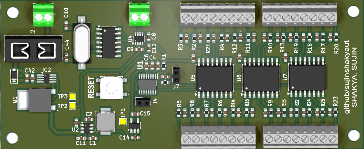
A compact multi-channel temperature sensing PCB built around the TI MSPM0C1104 microcontroller with CAN FD communication. Designed to be later integrated on a voltage tap board that mounts directly onto the Orion BMS module, providing up to 24 analog temperature inputs per tapboard or breakout board multiplexed through a 3 ADC channel with robust power protection for automotive and industrial environments.
Temperature Sensor Board

Table of Contents

Background

This is a redesigned temperature sensing board intended to be integrated with a voltage tap board on the Orion BMS module, providing cell temperature monitoring across the battery pack.

The main Orion BMS is limited to 8 internal thermistor inputs, which is insufficient for large-scale battery packs. To achieve full coverage, we integrated the Orion Thermistor Expansion Module, scaling our monitoring capacity to 60+ individual cells. This expansion node digitizes localized analog temperatures and broadcasts them via CANbus to the main unit. This architecture not only meets the capacity requirements of the accumulator but also ensures clean data transmission and minimizes wiring complexity within the high-voltage enclosure.

This is fine

The board consolidates power regulation, input protection, analog multiplexing, and CAN FD communication onto a single compact PCB. A three-stage power supply has been implemented due to potential 60V voltage spikes from the battery module. Power input is protected by an LM74500 ideal diode controller and an SMF24CA TVS diode, with the AP63205 buck converter stepping down to 5 V and a TPS7A03 LDO providing a clean 3.3 V rail. A fuse is included for extra protection.

The CLV4051A 8:1 analog multiplexer allows a single ADC input on the MSPM0C to scan up to 8 temperature sensor channels sequentially, reducing pin count. The MCP2517FD provides CAN FD connectivity over SPI.

NTC Thermistors & Steinhart-Hart

This board interfaces with Negative Temperature Coefficient (NTC) thermistors (typically 10 kΩ at 25°C). The thermistors are placed in a voltage divider circuit with a known 10 kΩ bias resistor. Because the resistance curve of an NTC is highly non-linear, the firmware utilizes the Steinhart-Hart equation for accurate conversion from resistance to temperature across the accumulator's operating range:

$$\frac{1}{T} = A + B \ln(R) + C (\ln(R))^3$$

Where:

  • T = Temperature in Kelvin
  • R = Measured resistance of the thermistor in Ohms
  • A, B, C = Steinhart-Hart coefficients provided by the thermistor manufacturer

The MCU reads the 12-bit ADC value, calculates the resistance R via the voltage divider equation, applies the Steinhart-Hart conversion to find Kelvin, and then broadcasts the Celsius equivalent over CAN FD.

Features

  • 24-channel analog temperature input via CLV4051A multiplexers
  • CAN FD communication (MCP2517FD over SPI) to Orion BMS
  • Wide input voltage range with reverse polarity and TVS protection
  • On-board buck + LDO three-stage power supply with 24V voltage regulation
  • High-accuracy NTC thermistor reading using Steinhart-Hart conversion
  • Screw terminal connectors
  • M3 mounting holes for panel or DIN mount

Contributing

Open an issue or pull request on GitHub.

Parts

100
QtyValueFootprintReferences
24470nFLibrary:C_0603_1608MetricC17, C18, C19, C20, C21, C22, C23, C24, C25, C26, C27, C28, C29, C30, C31, C32 +8
24680Library:R_0603_1608MetricR2, R10, R11, R12, R13, R14, R15, R16, R17, R18, R19, R20, R21, R22, R23, R24 +8
70.1µFLibrary:C_0603_1608MetricC6, C8, C9, C12, C13, C16, C40
51uFLibrary:C_0603_1608MetricC14, C15, C41, C42, C43
4MountingHoleLibrary:MountingHole_3.2mm_M3H1, H2, H3, H4
4Screw_Terminal_01x08Library:1725711J1, J2, J3, J6
3CLV4051ATDWRG4Q1Library:SOIC-16W_7.5x10.3mm_P1.27mmU5, U6, U7
3TestPointLibrary:TestPoint_Pad_1.5x1.5mmTP1, TP2, TP3
222pLibrary:C_0603_1608MetricC10, C44
222uFLibrary:C_0603_1608MetricC1, C3
2Conn_01x02_PinLibrary:PinSocket_1x02_P2.00mm_VerticalJ4, J7
2Screw_Terminal_01x02Library:1725656J5, J8
1100nLibrary:C_0603_1608MetricC2
110nLibrary:C_0603_1608MetricC7
110uLibrary:C_0603_1608Metric_Pad1.08x0.95mm_HandSolderC11
110uLibrary:C_0603_1608MetricC4
11MLibrary:R_0603_1608MetricR81
13568Library:Fuseholder_Blade_Mini_Keystone_3568F1
14.7μLibrary:inductorcustome27L1
147.5kLibrary:R_0603_1608MetricR1
1AP63205Library:TSOT-23-6U2
1HC49/4HSMXLibrary:830017146Y1
1LM74500QDDFRQ1Library:TSOT-23-8_HandSolderingIC2
1Littelfuse SMF24CALibrary:D_SOD-123FD1
1MCP2517FD-H/SLLibrary:Texas_DDF0008A_SOT-8_1.6x2.9mm_P0.65mmU4
1MCP2517FDT-H_SLLibrary:SOIC-14_3.9x8.7mm_P1.27mmU3
1MSPM0C1104SDGS20RLibrary:MSPMOCU1
1SUD20N10-66L-GE3Library:SUD20N1066LGE3Q1
1SW_PushLibrary:KSC251JSPDELTALFSSW1
1TPS7A03Library:SOT-23-5_HandSolderingIC1

Similar boards

  • 2 layers98.5 × 50 mmLV Sensor, the printed circuit board in 3D

    LV Sensor

    Manixh-S/CAN-FD-LV-Sensor-Board

    This LV Sensor Board is a custom, high-reliability low-voltage sensing module designed for the FSAE. This board measures both unipolar [0, 5V] and bipolar [−18, 18V] low-voltage signals across eight differential…

    97 parts
  • 2 layers77 × 74.5 mmBms, the printed circuit board in 3D

    Bms

    p0lyh3dron/tpl_interface

    My TPL interface for NXP's MC33664/33771C platform

    33 parts
  • 2 layers169.9 × 135.9 mmCircuits, the printed circuit board in 3D

    Circuits

    DVA490-474-Project-Course/SSL-Hardware-Development

    Contains all hardware related material. (No software).

    65 partsMIT
  • 4 layers33 × 65.5 mmOM FlexGrid Rigid PCB, the printed circuit board in 3D

    OM FlexGrid Rigid PCB

    Open-Muscle/OpenMuscle-FlexGrid

    60-sensor wearable with flexible PCB and pressure matrix

    65 parts19CERN-OHL-S-2.0
  • 4 layers75 × 35 mmLASK5-V3-0, the printed circuit board in 3D

    LASK5-V3-0

    Open-Muscle/OpenMuscle-LASK5

    Handheld labeler wand for training ML models on gesture inputs

    56 parts3CERN-OHL-S-2.0
  • 2 layers27.5 × 52 mmOM EPSC3-Micro, the printed circuit board in 3D

    OM EPSC3-Micro

    turfptax/OM-Dev-Kit

    Open Muscle Dev Kit (V0/V1): ESP32-C3 sensor-cell hardware (KiCad PCBs + gerbers) and MicroPython firmware for the OpenMuscle pressure-sensing platform.

    23 parts2
  • 2 layers27.5 × 52 mmOM EPSC3-Micro, the printed circuit board in 3D

    OM EPSC3-Micro

    Open-Muscle/OpenMuscle-Band

    Original OpenMuscle armband with 12 sensors (legacy design)

    22 parts1CERN-OHL-S-2.0
  • 2 layers26.1 × 40.6 mmCANFD Module, the printed circuit board in 3D

    CANFD Module

    TNCT-Mechatech/CANFD_Module

    SPI->CAN FDに変換するモジュール

    24 parts3Apache-2.0

Questions

How big is the Temp sense redesign PCB?

It measures 102.4 × 43 mm and has 2 copper layers, 1.6 mm thick.

What parts does the Temp sense redesign use?

100 parts, built around the MSPM0C1104SDGS20R, AP63205WU, CLV4051ATDWRG4Q1 and LM74500QDDFRQ1. The full list of its parts is on this page, with links to each part's symbol and footprint where PCBKit's library has them.

Where can I download the Temp sense redesign KiCad files?

From the sujinshakyaut/temp_sense_e27 repository on GitHub, at the commit this page was made from: the board is temp_sense_redesign.kicad_pcb and its schematic temp_sense_redesign.kicad_sch. PCBKit opens the board in the browser, with nothing to install.

Can I use the Temp sense redesign design in my own project?

Its repository states no licence, so its author keeps all rights: ask sujinshakyaut before reusing the design.