4 layers88.9 × 79.4 mm
Link
oats-center/avena-rs
Avena On The Road: Bringing pavement health data to your fingertips
170 parts3
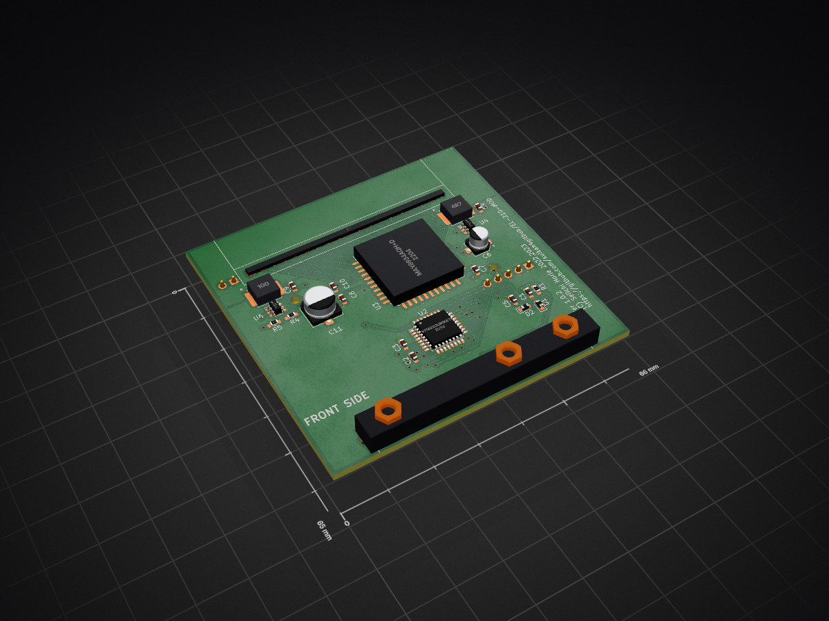
 suikan4github/EL-210-MOD3
Alternative circuit for SHARP EL-210 calculator
EL-210-MOD is an open-source printed circuit board by suikan4github, from the suikan4github/EL-210-MOD repository on GitHub, published under the MIT licence. It is a 2-layer board of 66 × 65 mm with 36 parts on 82 nets, routed with 341 tracks and 52 vias.
It is built around the STM32G0B1KET6, MAX6934AQH+D and TLV61046ADBV, with the TPS613221ADBV and MAX4719EUB+ among its other parts. Its parts include 11 capacitors, 6 ICs, 5 resistors, 3 connectors and 2 diodes. It belongs with the STM32 boards of this library.


Alternative circuit for SHARP EL-210/EL-215 calculator
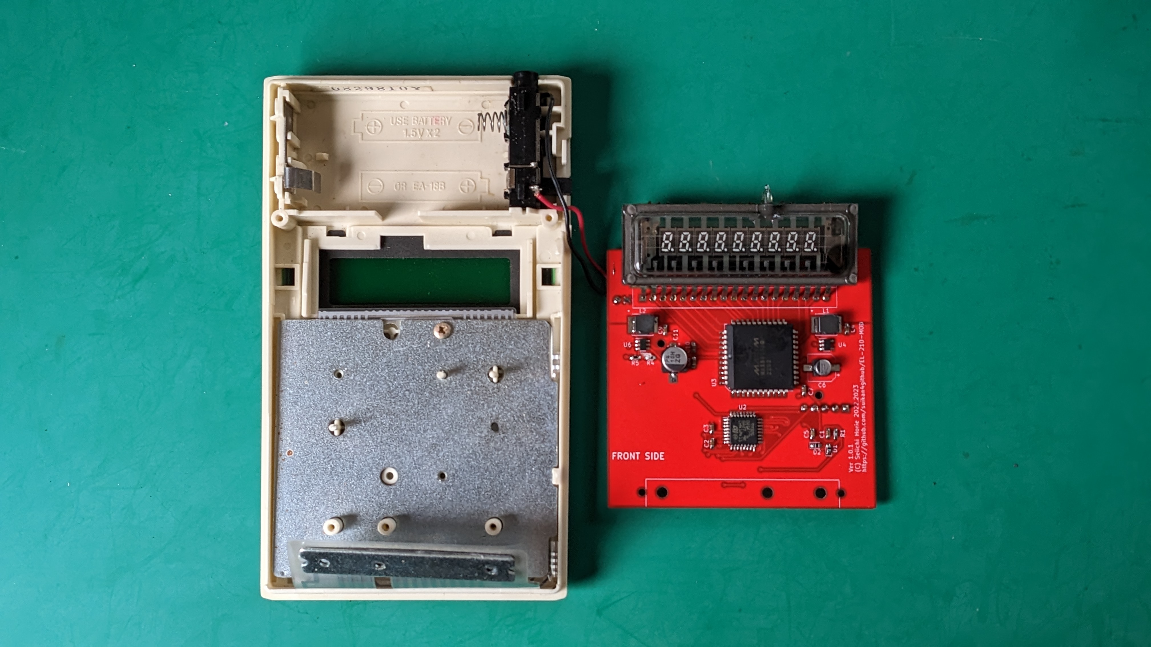
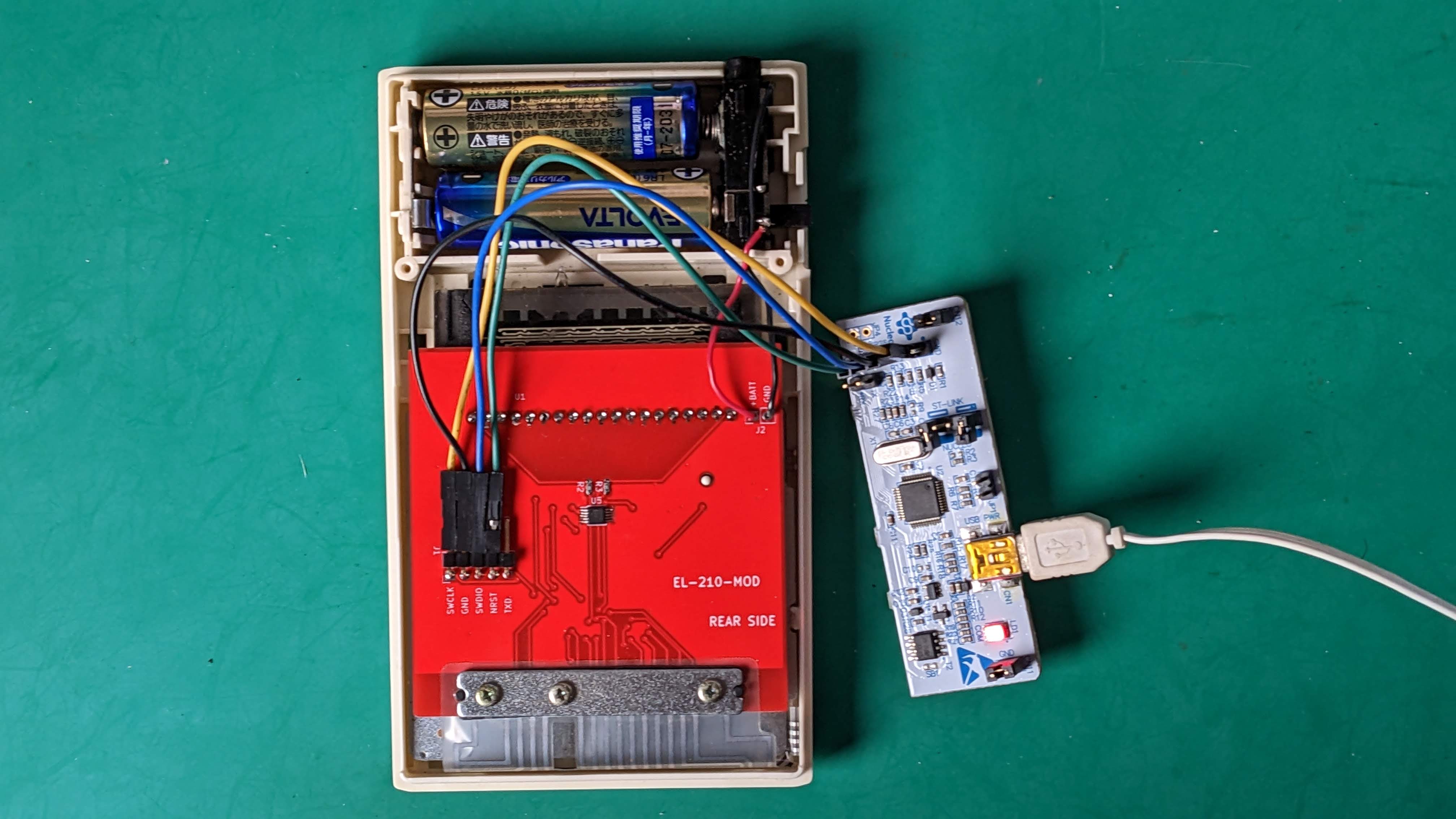
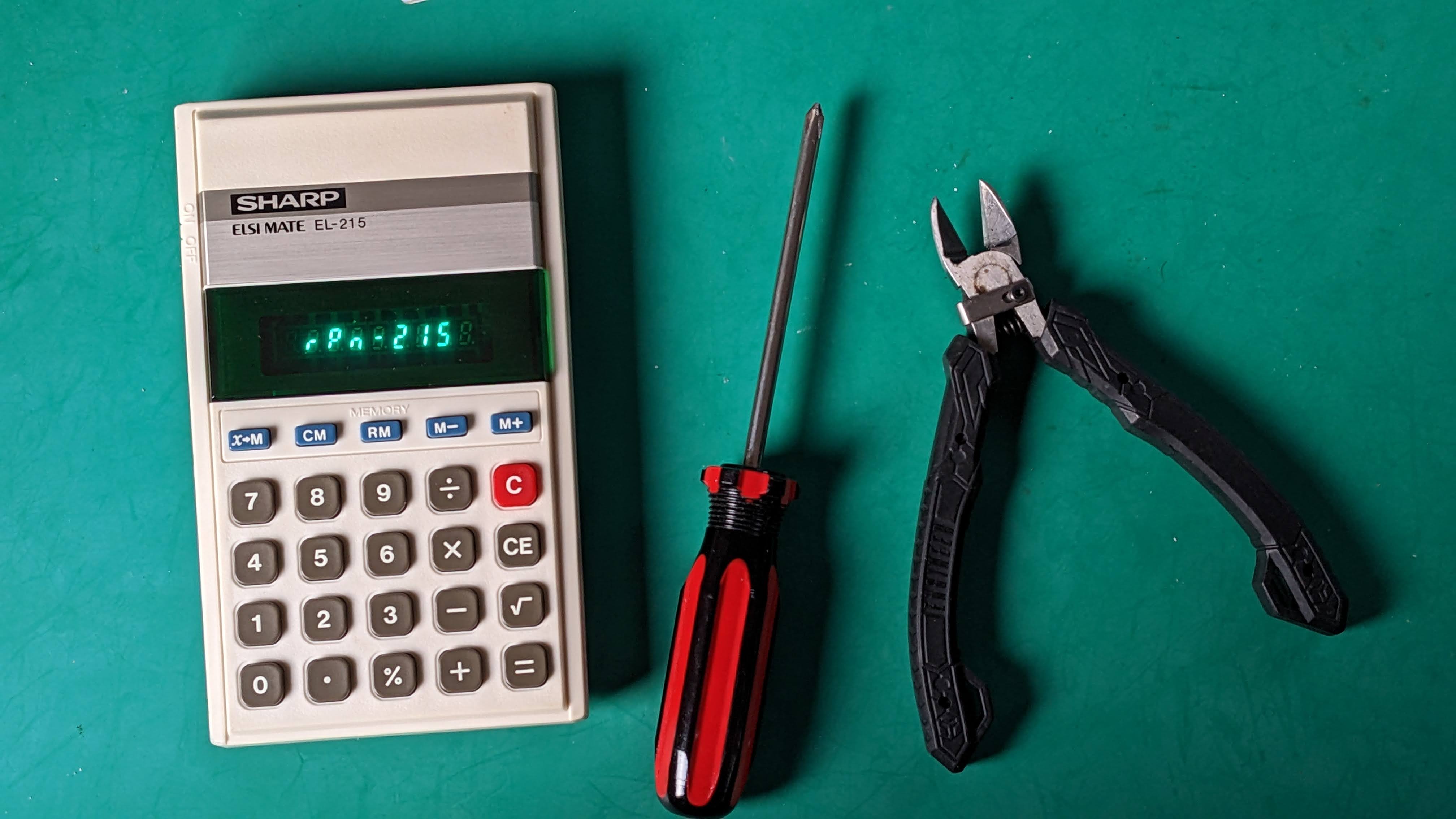
This is a circuit/board design for the alternate PCB for the SHARP EL-210/215 calculators. SHARP EL-210 series are manufactured around early 1980th. By using this alternate PCB, you can program any program as firmware of this classic VFD calculator.
There is an dedicated RPN firmware is located in the rpn2026 project.
To make your own RPN calculator, user must follow the procedure :
You can found additional design resources :
The VFD is 9-ST-20, manufactured by Futaba. The specification is not disclosed. Pin assignment has been investigated by LI2026ODP project.
The heater must be driven by differential alternate current. This is required to make the flat brightness between right-end and left-end of the VFD. If you drive the heater by DC, the voltage slope of the heater will make the slop of the brightness.
The analog switch provide the low voltage drop out current switching. The timing is made by MCU timer.
The grid bias is required 4. Because the balanced drive of the heater makes 1.65V grid bias, we need only 2.5V more.
The key matrix has been investigated by also LI2026ODP project.
The EL-21x series key matrix doesn't have any protection diode. Thus, to prevent the signal shortage, the GPIO pins for the key matrix have to be configured :
To check the button pushed, output the "L" from the Row. If the Column get "L", the button is pushed.
| Row | Column 0 | Column 1 | Column 2 |
|---|---|---|---|
| 0 | CE | X->M | 0 |
| 1 | 7 | 4 | |
| 2 | CM | 8 | 1 |
| 3 | . | 5 | % |
| 4 | + | RM | 2 |
| 5 | C | 9 | = |
| 6 | / | M- | |
| 7 | * | 6 | 3 |
| 8 | - | M+ | sqrt |
To supply the 24V to VFD, set EN24 signal to "H".
In the case you order the PCB to a board manufacturer, you must specify the PCB thinness as 1.0mm. The standard 1.3mm is too thick.
The Grid bias is not deep as expected. It is -0.9V while expected -2.5v. It is left untouched because it is not problematic.
| Qty | Value | Footprint | References |
|---|---|---|---|
| 7 | 0.1u | Capacitor_SMD:C_0603_1608Metric_Pad1.08x0.95mm_HandSolder | C2, C3, C4, C7, C8, C9, C10 |
| 3 | 18 | Resistor_SMD:R_0603_1608Metric_Pad0.98x0.95mm_HandSolder | R1, R2, R3 |
| 3 | hole_2.8mm | hole:hole_2.8mm | H4, H5, H6 |
| 2 | 1u | Capacitor_SMD:C_0603_1608Metric_Pad1.08x0.95mm_HandSolder | C1, C5 |
| 2 | D_Schottky | Diode_SMD:D_0603_1608Metric_Pad1.05x0.95mm_HandSolder | D1, D2 |
| 2 | hole_1.9mm | hole:hole_1.8mm | H3, H7 |
| 2 | hole_2.0mm | hole:hole_2.0mm | H1, H2 |
| 1 | 10u | Capacitor_SMD:CP_Elec_6.3x3.9 | C11 |
| 1 | 10uH | project_lib:LQH5BPN100M38L | L2 |
| 1 | 2.15k | Resistor_SMD:R_0603_1608Metric_Pad0.98x0.95mm_HandSolder | R5 |
| 1 | 22u | Capacitor_SMD:CP_Elec_4x3.9 | C6 |
| 1 | 4.7uH | project_lib:LQH5BPN100M38L | L1 |
| 1 | 61.9k | Resistor_SMD:R_0603_1608Metric_Pad0.98x0.95mm_HandSolder | R4 |
| 1 | 9-ST-20 | 9-ST-20:9-ST-20 | U1 |
| 1 | Conn_01x02 | Connector_PinHeader_2.54mm:PinHeader_1x02_P2.54mm_Vertical | J2 |
| 1 | Conn_01x05 | Connector_PinHeader_2.54mm:PinHeader_1x05_P2.54mm_Horizontal | J1 |
| 1 | EL-210-KEY | EL-210-KEY:EL-210-KEY | P1 |
| 1 | MAX4719EUB+ | Package_SO:MSOP-10_3x3mm_P0.5mm | U5 |
| 1 | MAX6934AQH+D | plcc44_hs:PLCC44_handsoldering | U3 |
| 1 | STM32G0B1KET6 | Package_QFP:LQFP-32_7x7mm_P0.8mm | U2 |
| 1 | TLV61046ADB | Package_TO_SOT_SMD:SOT-23-6 | U6 |
| 1 | TPS613221ADBV | Package_TO_SOT_SMD:SOT-23-5 | U4 |
It measures 66 × 65 mm and has 2 copper layers, 1.6 mm thick.
36 parts, built around the STM32G0B1KET6, MAX6934AQH+D, TLV61046ADBV and TPS613221ADBV. The full list of its parts is on this page, with links to each part's symbol and footprint where PCBKit's library has them.
From the suikan4github/EL-210-MOD repository on GitHub, at the commit this page was made from: the board is EL-210-MOD.kicad_pcb and its schematic EL-210-MOD.kicad_sch. PCBKit opens the board in the browser, with nothing to install.
Its repository publishes it under the MIT licence: you may reuse it on that licence's terms (keep the author's notice, and for a copyleft licence share your changes alike).
oats-center/avena-rs
Avena On The Road: Bringing pavement health data to your fingertips

cepr/daly-to-lithium-balance-adapter
Replacement traction battery for a 2018 Energica Ego. The original Lithium Balance s-BMS master (BMCU) stays in the bike.


netz39/Stepper-Locking-System
Contains encoder & processor boards for closed-loop stepper motor angle control. Steering the key/door knob with the might of stepper motors.

lucasnoce/IC-LevelSensor_v2
Water level sensor with NBIoT data transmission

rappet/ferris-badge
Small badge running on a coin cell using a STM32L031G6U with embassy.


RICCIARDI-Adrien/Chip8_Console
A Chip-8 / Super Chip-8 console powered by a 8-bit PIC18 microcontroller.