2 layers36 × 36 mm
Signal splitter
netz39/Stepper-Locking-System
Contains encoder & processor boards for closed-loop stepper motor angle control. Steering the key/door knob with the might of stepper motors.
10 partsMIT

 netz39/Stepper-Locking-System
Contains encoder & processor boards for closed-loop stepper motor angle control. Steering the key/door knob with the might of stepper motors.
StepperLockingSystem is an open-source printed circuit board by netz39, from the netz39/Stepper-Locking-System repository on GitHub, published under the MIT licence. It is a 4-layer board of 54 × 84 mm with 107 parts on 65 nets, routed with 598 tracks and 348 vias.
It is built around the STM32G0B1KET6, USBLC6-2SC6 and 24LC64(LX), with the TMC2209-LA, BAT54WHE3-TP and ESD9X12ST5G among its other parts. Its parts include 35 capacitors, 24 resistors, 9 connectors, 7 ICs and 4 diodes. It belongs with the robots and motor control boards and the STM32 boards of this library.


Steering the key/door knob with the might of stepper motors. See the Wiki (german) for more details and an overview.
This is forked from https://github.com/sprenger120/StepperServo.
The firmware written in C++ is here.
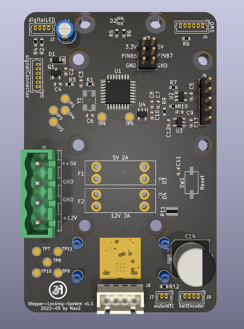
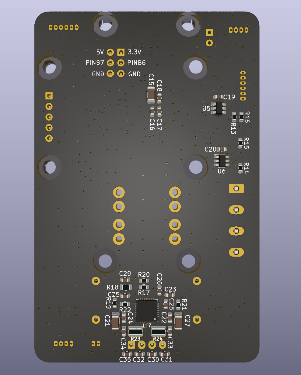
| Qty | Value | Footprint | References |
|---|---|---|---|
| 11 | TestPoint | TestPoint:TestPoint_Pad_D2.0mm | TP1, TP2, TP3, TP4, TP5, TP6, TP7, TP8, TP9, TP10, TP11 |
| 9 | 100nF | Capacitor_SMD:C_0603_1608Metric | C5, C7, C8, C10, C11, C16, C17, C19, C20 |
| 8 | MountingHole_Pad | extraFootprints:MountingHole_3.2mm_M3_ISO7380_Keepout | H1, H2, H3, H4, H5, H6, H7, H8 |
| 4 | 100nF 16V | Capacitor_SMD:C_0603_1608Metric | C22, C23, C24, C25 |
| 4 | 1uF | Capacitor_SMD:C_0603_1608Metric | C4, C12, C13, C18 |
| 4 | 2k2 | Resistor_SMD:R_0603_1608Metric | R2, R4, R7, R10 |
| 4 | 470pF 100V | Capacitor_SMD:C_0603_1608Metric | C30, C31, C32, C35 |
| 4 | 5k6 | Resistor_SMD:R_0603_1608Metric | R13, R14, R15, R16 |
| 2 | 100nF 35V | Capacitor_SMD:C_0603_1608Metric | C33, C34 |
| 2 | 10k | Resistor_SMD:R_0603_1608Metric | R9, R12 |
| 2 | 10uF 16V | Capacitor_SMD:C_1206_3216Metric | C21, C27 |
| 2 | 150m | Resistor_SMD:R_0612_1632Metric | R23, R24 |
| 2 | 15pF | Capacitor_SMD:C_0603_1608Metric | C3, C6 |
| 2 | 1k | Resistor_SMD:R_0603_1608Metric | R3, R20 |
| 2 | 1uF 16V | Capacitor_SMD:C_0603_1608Metric | C2, C29 |
| 2 | 22k | Resistor_SMD:R_0603_1608Metric | R21, R22 |
| 2 | USBLC6-2SC6 | Package_TO_SOT_SMD:SOT-23-6 | U5, U6 |
| 1 | 1.1R 0.5W | Resistor_SMD:R_0805_2012Metric | R18 |
| 1 | 100R | Resistor_SMD:R_0603_1608Metric | R1 |
| 1 | 100k | Resistor_SMD:R_0603_1608Metric | R8 |
| 1 | 100m 0.5W | Resistor_SMD:R_0612_1632Metric | R11 |
| 1 | 10uF | Capacitor_SMD:C_1206_3216Metric | C15 |
| 1 | 12V 2A | extraFootprints:KEYSTONE-FUSE-3557-2 | F2 |
| 1 | 13k | Resistor_SMD:R_0603_1608Metric | R19 |
| 1 | 180uF | Capacitor_THT:CP_Radial_D5.0mm_P2.50mm | C1 |
| 1 | 2.2uF 16V | Capacitor_SMD:C_0603_1608Metric | C26 |
| 1 | 220R | Resistor_SMD:R_0603_1608Metric | R5 |
| 1 | 22nF 50V | Capacitor_SMD:C_0603_1608Metric | C28 |
| 1 | 24LC64 | Package_TO_SOT_SMD:SOT-23-5 | U2 |
| 1 | 330uF 16V | Capacitor_SMD:CP_Elec_10x10.5 | C14 |
| 1 | 390R | Resistor_SMD:R_0603_1608Metric | R6 |
| 1 | 470pF | Capacitor_SMD:C_0603_1608Metric | C9 |
| 1 | 4k7 | Resistor_SMD:R_0603_1608Metric | R17 |
| 1 | 5Pin DuPont 2.54mm | Connector_PinHeader_2.54mm:PinHeader_1x05_P2.54mm_Vertical | J5 |
| 1 | 5V 2A | extraFootprints:KEYSTONE-FUSE-3557-2 | F1 |
| 1 | 6Pin DuPont 2.56mm | Connector_PinHeader_2.54mm:PinHeader_2x03_P2.54mm_Vertical | J3 |
| 1 | ABM3B-16MHz | Crystal:Crystal_SMD_Abracon_ABM3B-4Pin_5.0x3.2mm | Y1 |
| 1 | BAT54WHE3-TP | Diode_SMD:D_SOD-123 | D1 |
| 1 | ESD9X12ST5G | Diode_SMD:D_SOD-923 | D4 |
| 1 | ESD9X5.0ST5G | Diode_SMD:D_SOD-923 | D3 |
| 1 | INA180A1 | Package_TO_SOT_SMD:SOT-23-5 | U4 |
| 1 | IRLML0030 | Package_TO_SOT_SMD:SOT-23 | Q1 |
| 1 | LTST-C195TGKRKT | extraFootprints:LED_LiteOn_LTST-C195TGKRKT | D2 |
| 1 | Reset | extraFootprints:PTS636_F-leads | SW1 |
| 1 | STM32G0B1KET | Package_QFP:LQFP-32_7x7mm_P0.8mm | U1 |
| 1 | SWD | Connector_Molex:Molex_PicoBlade_53047-0610_1x06_P1.25mm_Vertical | J4 |
| 1 | Stepper | Connector_JST:JST_XH_B4B-XH-A_1x04_P2.50mm_Vertical | J8 |
| 1 | TC1185 | Package_TO_SOT_SMD:SOT-23-5 | U3 |
| 1 | TMC2209-LA | Package_DFN_QFN:QFN-28-1EP_5x5mm_P0.5mm_EP3.35x3.35mm_ThermalVias | U7 |
| 1 | digitalLED | Connector_Molex:Molex_PicoBlade_53047-0410_1x04_P1.25mm_Vertical | J2 |
| 1 | hallEncoder | Connector_Molex:Molex_PicoBlade_53047-0410_1x04_P1.25mm_Vertical | J9 |
| 1 | motorNTC | Connector_Molex:Molex_PicoBlade_53047-0210_1x02_P1.25mm_Vertical | J7 |
| 1 | powerConnector | Connector_Phoenix_MSTB:PhoenixContact_MSTBVA_2,5_4-G-5,08_1x04_P5.08mm_Vertical | J6 |
| 1 | signalConnector | Connector_Molex:Molex_PicoBlade_53047-0610_1x06_P1.25mm_Vertical | J1 |
The 103 most common of 107 parts.
It measures 54 × 84 mm and has 4 copper layers, 3.66 mm thick.
107 parts, built around the STM32G0B1KET6, USBLC6-2SC6, 24LC64(LX) and TMC2209-LA. The full list of its parts is on this page, with links to each part's symbol and footprint where PCBKit's library has them.
From the netz39/Stepper-Locking-System repository on GitHub, at the commit this page was made from: the board is StepperLockingSystem.kicad_pcb and its schematic StepperLockingSystem.kicad_sch. PCBKit opens the board in the browser, with nothing to install.
Its repository publishes it under the MIT licence: you may reuse it on that licence's terms (keep the author's notice, and for a copyleft licence share your changes alike).
netz39/Stepper-Locking-System
Contains encoder & processor boards for closed-loop stepper motor angle control. Steering the key/door knob with the might of stepper motors.

netz39/cyberdesk
Cyberdesk ist ein modulares Projekt, um unseren Basteltisch modern zu gestalten. Es integriert u.a. eine steuerbare Beleuchtung.


GuavTek/M2IDI_TANGLE_HW
A multiplexer module for the M2IDI system


oats-center/avena-rs
Avena On The Road: Bringing pavement health data to your fingertips


cepr/daly-to-lithium-balance-adapter
Replacement traction battery for a 2018 Energica Ego. The original Lithium Balance s-BMS master (BMCU) stays in the bike.
