4 layers194.3 × 92.8 mm
 sufst/pcb19
Monorepo for all schematics and PCB designs
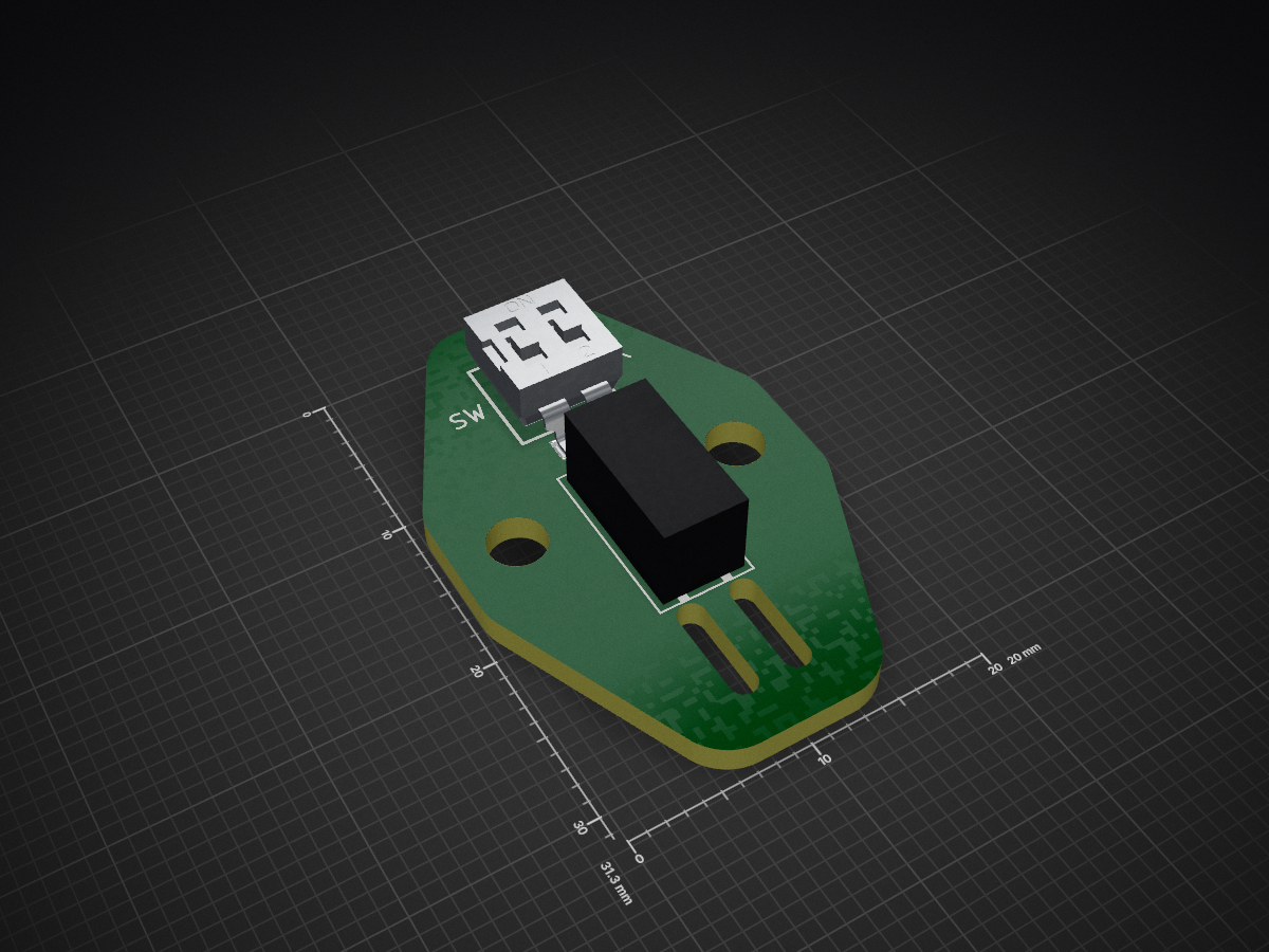
Segment switch is an open-source printed circuit board by sufst, from the sufst/pcb repository on GitHub, published under the GPL-3.0 licence. It is a 2-layer board of 20 × 31.3 mm with 4 parts on 2 nets, routed with 8 tracks and 0 vias.
Its parts include 1 connector and 1 switch.
Central repository of all schematics and PCB design files.
| Folder | Project | Project Code |
|---|---|---|
| ail | Accumulator Indicator Light Logic | ail |
| ail-led | Accumulator Indicator Light Led | ail-led |
| batak | Batak Game (non-car) | batak |
| break-light | Rear Break Light | break-light |
| bspd | Brake System Plausibility Device | bspd |
| can-node | Voltage Reader and Broadcaster | can-node |
| curr-amp | Current Sensor Amplifier | curr-amp |
| dash | Dashboard | dash |
| discharge | Discharge Relay Breakout | discharge |
| hv-sense | High Voltage Sense | hvs |
| latching | Latch Circuit | latching |
| loom* | Loom Design | loom |
| lvbms | Low Voltage Battery Management System | lvbms |
| precharge | Precharge Controller | precharge |
| segment | Segment | segment |
| telemetry | On-Car Telemetry | telemetry |
| test-rig | PCB Test / Demo Rig | test |
| top-level* | Full Car Schematic | |
| trc | TSAC Relay Controller | trc |
| tsal | Tractive System Active Light | tsal |
| vcu | Vehicle Control Unit | vcu |
We design our PCBs in KiCad (version 8+).
*Moved to https://github.com/sufst/loom
Files that should be in this repo, under version control:
.kicad_pro)..kicad_sch)..kicad_pcb)..kicad_mod)..kicad_sym).fp-lib-table).sym-lib-table)..step files)..asc files from LTSpice).Files that should never be in here:
.kicad_prl).<project name>-backups, .bak .bck -bak files).fp-info-cache).The .gitignore should prevent the addition of files we don't want to keep in here, but before you commit make sure to do a quick check of what is actually being added.
The common folder is used for resources which can be shared across multiple projects. This includes:
images subdirectory).step subdirectory).sufst-lib.kicad_sym).sufst-lib.pretty).sheet-layout.kicad_wks).Note: Since projects were previously in their own individual repos, many designs still have their own libraries, step files, etc. These will gradually be migrated to the SUFST library.
When you configure the library paths for a project (sym-lib-table and fp-lib-table data), make sure to always use a path relative to the project with the ${KIPRJMOD} substitution.
${KIPRJMOD}/../common/sufst-lib.kicad_sym/Users/<your name>/Documents/sufst/pcb/common/sufst-lib.kicad_symIf an absolute path is used, when someone else opens the project that path will not exist and the library paths will not be valid. -lib-table files should never contain an absolute path.
It is not possible to resolve merge conflicts within individual design files, which is an unfortunate limitation of using git with KiCad. While KiCad files are in a text format, they aren't really designed to be edited manually. It is therefore essential that only one person is editing a particular file in a project at a time (including the shared library). Once someone starts working on a file, until it is merged into the main branch nobody else can edit that file. A good way to get round this is to use the "hierarchical sheets" feature to divide schematics into multiple files (if it can be done in a logical way).
When a PCB is fabricated, a new 'release' for the given project should be
created and stored within this repo in the releases/<PROJECT NAME> folder.
This folder should contain the latest version (and ONLY the latest version) of
the following files:
fabrication.zip.Schematic.pdf).Layout.pdf).ibom.html).Additionally, a file called info (no extension) should be created (if it
doesn't already exist) containing release information in the following format:
version: <VERSION NUMBER>
date: <RELEASE DATE>
fabrication: <COMPANY>
Version numbers should be in the format v1.0.1 and dates should be in the
format YYYY-MM-DD. For example:
version: v1.0.1
date: 2023-01-23
fabrication: JLCPCB
The release folder for a project should then have the following structure and file names:
<PROJECT NAME>
├── Layout.pdf
├── Schematic.pdf
├── fabrication.zip
├── ibom.html
└── info
When creating a new release, make sure to overwrite/replace all the existing files.
The release commit should then be tagged with the following command:
git tag <PROJECT CODE>-<VERSION_NUMBER>Tagging should be done after merging to main! Example command:
git tag segment-v1.0.1To push tags to GitHub:
git push --tags| Qty | Value | Footprint | References |
|---|---|---|---|
| 2 | MountingHole | MountingHole:MountingHole_3.2mm_M3 | H1, H2 |
| 1 | Conn_01x02 | SUFST:Conn2_SMD | J1 |
| 1 | SW_SPST | SUFST:24549852 | SW1 |
It measures 20 × 31.3 mm and has 2 copper layers, 1.6 mm thick.
4 parts. The full list of its parts is on this page, with links to each part's symbol and footprint where PCBKit's library has them.
From the sufst/pcb repository on GitHub, at the commit this page was made from: the board is segment-switch/segment-switch.kicad_pcb. PCBKit opens the board in the browser, with nothing to install.
Its repository publishes it under the GPL-3.0 licence: you may reuse it on that licence's terms (keep the author's notice, and for a copyleft licence share your changes alike).


joypad-ai/joypad-os
Universal controller firmware for building adapters, dongles, and custom controllers.


hackclub/OnBoard
💡 Join 1,000 teenagers and make your first PCB with a $100 grant!

tardate/LittleArduinoProjects
a collection of "Little Electronic & Arduino Projects", most involving electronics or an Arduino in one way or another!

drandyhaas/KiCadRoutingTools
A set of Python/Rust tools to aid routing in KiCad

osy/XG_Mobile_Station
Open source eGPU dock for ROG Ally and ROG Flow

Luos-io/luos_engine
Open-source and real-time orchestrator for cyber-physical-systems, to easily design, test and deploy embedded applications and digital twins.

NVNTLabs/switch2-SDEX2M2
Micro SD Express to M.2 NVME Adapter for Nintendo Switch 2