4 layers50 × 60 mm
Jtag ft
BroGamesJaj/jtag-ft
A simple FT2232HP board to program and debug fpgas and other jtag capable hardware.
62 parts
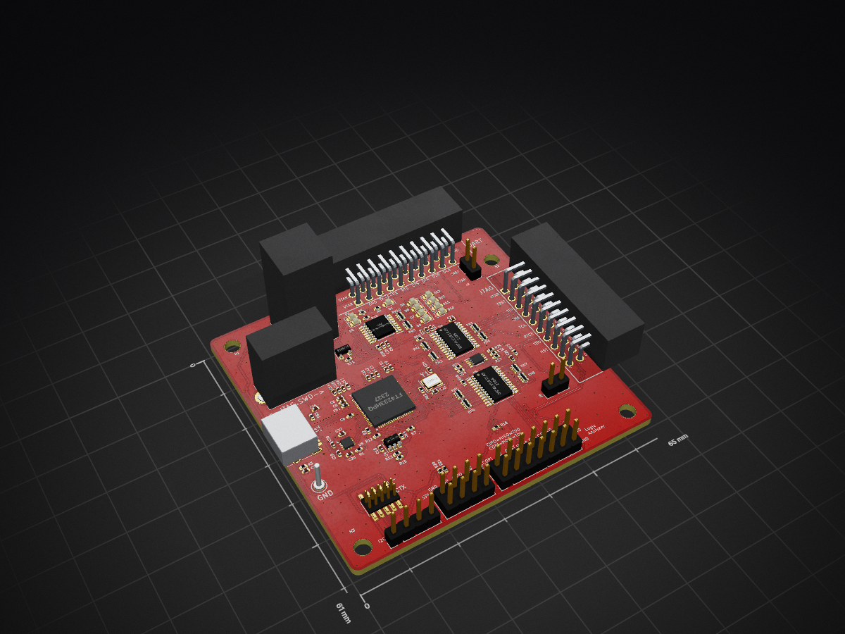
 suddenabnormalsecrets/Serberus
Multi-headed and Multi-Protocol embedded system hacking tool.
Serberus is an open-source printed circuit board by suddenabnormalsecrets, from the suddenabnormalsecrets/Serberus repository on GitHub, published under the Apache-2.0 licence. It is a 4-layer board of 65 × 61 mm with 108 parts on 154 nets, routed with 1,321 tracks and 350 vias.
It is built around the SN74LVC8T245PW, 74HCT595PW-Q100,11 and 93LC66BT-I/OT, with the AP7365-18WG, AP7365-33WG and FT4233HPQ among its other parts. Its parts include 31 capacitors, 26 resistors, 11 diodes, 9 ICs and 9 connectors. It belongs with the FPGA and CPLD boards of this library.


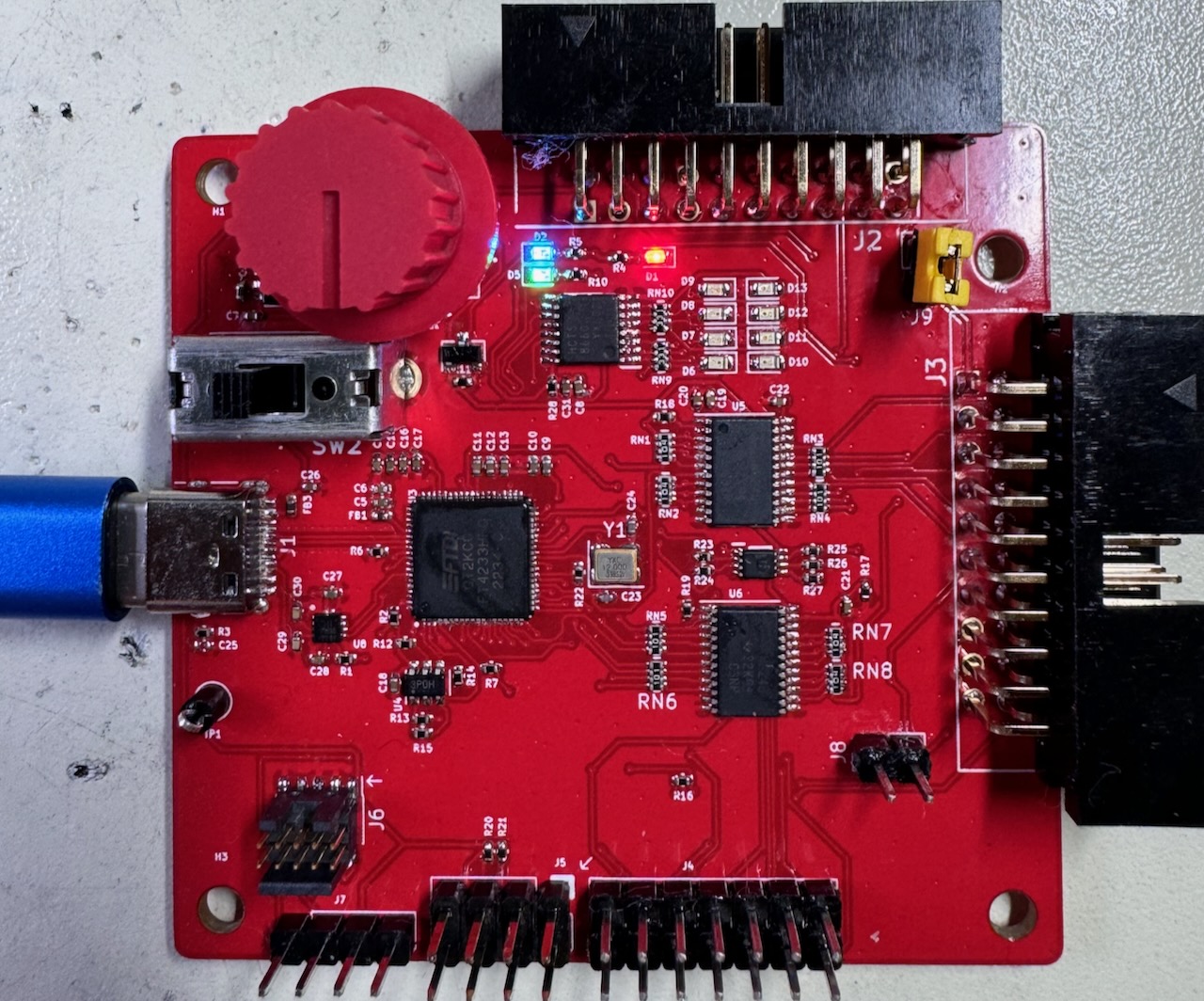
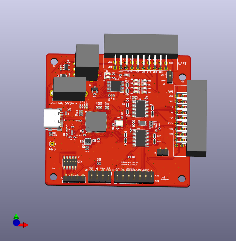
No drivers should be required, the FTDI devices are supported by most operating systems. The UART ports will work right away with screen, putty or your favorite serial console or serial access application such as OPENOCD.
The Serberus is based on a couple of earlier FTDI USB to TTL tools, the TIMEP and the TIGARD. The items below are some of the major changes from those designs.
When you plug in the Serberus, your system will be recognize the FTDI chip and the 4 serial ports.
The first, third and forth serial ports are intended for UART. You can use your favorite serial access tool, (Putty, screen) to access them as you would any other USB to serial device
example
screen /dev/ttyUSB0 {baudrate}
I need to do a little more work here as most of the tools like pyftdi and flashrom do not look for the FT4233. pyftdi should work with --vidpid flag and the value 0403:6041. You may need to change udev permissions
Details coming soon
Switch 1 is the rotary target voltage select switch, it has 4 positions. The first position is intended to match the voltage of your target and should rarely be needed, however it is included for those one-off scenarios where your target has a strange voltage between 1v6 and 5v5 but will not work with the provided levels. It will also adapt if your target changes voltage during the power up process. (I encountered this only once in all my years of testing.) J9 must have a jumper on it to make this connection.
The remaining 3 positions match the likely voltages of 1v8, 3v3 and 5v. Ideally in your workflow you will test your target and know what voltage level is appropriate. This switch works by taking the output of the voltage regulators U1, U2 or the 5v VBUS voltage and sending it to the level shifters VREF pin, to match the logic level of these signals.
| Position | Function |
|---|---|
| 1 | VTARGET |
| 2 | 1v8 |
| 3 | 3v3 |
| 4 | 5v |
Switch 2 is for combining various inputs to allow the second serial port to be used for JTAG, SPI, SWD and I2C. Switch to the left is for JTAG and SPI, separating the necessary TX and RX pins while the right position combines them for SWD and I2C.
connect VREF to VTARGET, allowing you to take the voltage level of your target and use that as the voltage level of the level shifters. J8 must have a jumper in place and SW1 must be in the first position for this feature to function.
For iCE FPGA programming, I added this feature from the TIGARD as it was an easy feature to include for a minimal cost. Close the jumper to connect UARTA_RX and Misc_RX, make sure SW2 is in JTAG mode.
The top connector has 3 UART connections, it is a standard 20 pin flat cable connector. The first UART has all 7 signal pins connected, for those rare instances where they are needed. The first UART is mapped to the first 4233 channel.
The second and third UARTS are mapped to the 3rd and 4th channels ports, as the second is used by the combined JTAG/SWD/I2C and SPI port. These ports only have TX and RX connected.
| Pin | Function |
|---|---|
| 1 | VTARGET |
| 2 | VTARGET |
| 3 | GND |
| 4 | TX-C |
| 5 | TX-A |
| 6 | RX-C |
| 7 | RX-A |
| 8 | GND |
| 9 | RTS-A |
| 10 | NC |
| 11 | CTS-A |
| 12 | RX-D |
| 13 | DTR-A |
| 14 | VTARGET |
| 15 | DSR-A |
| 16 | TX-D |
| 17 | DCD-A |
| 18 | RX-D |
| 19 | NC |
| 20 | GND |
The JTAG header is presented on J3, the right side of the board opposite the USB connector. The connector is a 20 Pin standard pitch Flat cable style. It is intended to match the Segger J-LINK pinout as much as possible, making it easier to use the many J-Link connectors to make a direct connection to an accessible header on your target.
| Pin | Function |
|---|---|
| 1 | VTARGET |
| 2 | NC |
| 3 | TRST |
| 4 | GND |
| 5 | TDI |
| 6 | GND |
| 7 | TMS |
| 8 | GND |
| 9 | TCK |
| 10 | GND |
| 11 | MISC_RX* |
| 12 | GND |
| 13 | TDO |
| 14 | GND |
| 15 | SRST |
| 16 | GND |
| 17 | NC |
| 18 | GND |
| 19 | NC |
| 20 | GND |
*Connected to BDBUS 6 as an input on the FT4233, only needed for bizarre on-off connections, for most purposes, leave as NC.
SW2 in leftmost position (1)
| Pin | Function |
|---|---|
| 1 | CS |
| 2 | VTARGET |
| 3 | CIPO/MISO |
| 4 | WP (PULLUP) |
| 5 | EN (PULLUP) |
| 6 | CLK |
| 7 | GND |
| 8 | COPI/MOSI |
SW2 in rightmost position (2)
| Pin | Function |
|---|---|
| 1 | SCL |
| 2 | SDA |
| 3 | VTARGET |
| 4 | GND |
A 10 pin cortex debug connector is present and will enable an easy connection to this common debug connector.
| Pin | Function |
|---|---|
| 1 | VTARGET |
| 2 | CORTEX PIN 2 |
| 3 | GND |
| 4 | TCK |
| 5 | GND |
| 6 | TDO |
| 7 | NC |
| 8 | TDI |
| 9 | GND |
| 10 | SRST |
The 14 pin header at the bottom next to the SPI and I2C connectors replicates most of the signal lines for easy connection to a logic analyzer or digital MSO lines of an oscilloscope. The pin header is standard 2.54mm pitch to easily connect using standard Dupont style jumper wires.
| Pin | Function |
|---|---|
| 1 | CLK |
| 2 | COPI/TDI |
| 3 | CIPO/TDO/SWDIO |
| 4 | TMS/CS |
| 5 | TRST |
| 6 | SRST |
| 7 | TX-A |
| 8 | RX-A |
| 9 | TX-C |
| 10 | RX-C |
| 11 | TX-D |
| 12 | RX-D |
| 13 | GND |
| 14 | GND |
The FT4233 is capable of power delivery (PD) and the design includes a DPO2036 for OVP. No other PD features have been added and the FTDI settings are at default. Power delivery is something that could be added but is well beyond the scope of this device for its initial release. Please feel free to experiment with forked designs.
Licensed under the Apache License, Version 2.0 (the "License");
you may not use this file except in compliance with the License.
You may obtain a copy of the License at

    https://www.apache.org/licenses/LICENSE-2.0

Unless required by applicable law or agreed to in writing, software
distributed under the License is distributed on an "AS IS" BASIS,
WITHOUT WARRANTIES OR CONDITIONS OF ANY KIND, either express or implied.
See the License for the specific language governing permissions and
limitations under the License.| Qty | Value | Footprint | References |
|---|---|---|---|
| 18 | 100n | Capacitor_SMD:C_0402_1005Metric | C5, C11, C12, C13, C14, C15, C16, C17, C18, C19, C20, C21, C22, C26, C28, C31 +2 |
| 13 | 10k | Resistor_SMD:R_0402_1005Metric | R1, R2, R7, R11, R12, R13, R14, R18, R19, R20, R21, R27, R28 |
| 7 | 2u2 | Capacitor_SMD:C_0402_1005Metric | C1, C2, C3, C4, C6, C9, C10 |
| 5 | GREEN | LED_SMD:LED_0603_1608Metric | D5, D7, D9, D11, D13 |
| 4 | 100 | Serberus:R_Array_Convex_4x0402_RoundRect | RN3, RN4, RN5, RN6 |
| 4 | 100k | Serberus:R_Array_Convex_4x0402_RoundRect | RN1, RN2, RN7, RN8 |
| 4 | 330 | Resistor_SMD:R_0402_1005Metric | R4, R5, R10, R16 |
| 4 | MountingHole | MountingHole:MountingHole_3.2mm_M3_ISO7380 | H1, H2, H3, H4 |
| 4 | RED | LED_SMD:LED_0603_1608Metric | D6, D8, D10, D12 |
| 2 | 100 | Resistor_SMD:R_0402_1005Metric | R25, R26 |
| 2 | 100k | Resistor_SMD:R_0402_1005Metric | R23, R24 |
| 2 | 1M | Resistor_SMD:R_0402_1005Metric | R3, R17 |
| 2 | 2k2 | Resistor_SMD:R_0402_1005Metric | R15, R22 |
| 2 | 30pF | Capacitor_SMD:C_0402_1005Metric | C23, C24 |
| 2 | 330 | Serberus:R_Array_Convex_4x0402_RoundRect | RN9, RN10 |
| 2 | 330p | Capacitor_SMD:C_0402_1005Metric | C29, C30 |
| 2 | 600R, 0.5A | Inductor_SMD:L_0402_1005Metric | FB1, FB3 |
| 2 | SN74LVC8T245 | Package_SO:TSSOP-24_4.4x7.8mm_P0.65mm | U5, U6 |
| 1 | 12MHz | Serberus:Crystal_SMD_3225-4Pin_3.2x2.5mm_RoundRect | Y1 |
| 1 | 12k, 1% | Resistor_SMD:R_0402_1005Metric | R6 |
| 1 | 1u | Capacitor_SMD:C_0402_1005Metric | C27 |
| 1 | 74HCT595PW-Q100,11 | Serberus:SOP65P640X110-16N | U9 |
| 1 | 93LC66BT-I/OT | Serberus:SOT-23-6_RoundRect | U4 |
| 1 | AP7365-18 | Serberus:SOT-23-5_RoundRect | U1 |
| 1 | AP7365-33 | Serberus:SOT-23-5_RoundRect | U2 |
| 1 | BLUE | LED_SMD:LED_0603_1608Metric | D2 |
| 1 | BSH103 | Serberus:SOT-23_RoundRect | Q1 |
| 1 | CORTEX | Serberus:PinHeader_2x05_P1.27mm_Vertical_SMD | J6 |
| 1 | DNP | Capacitor_SMD:C_0402_1005Metric | C25 |
| 1 | DPO2036DBB-7 | Serberus:QFN45P200X200X65-13N | U8 |
| 1 | FT4233HPQ | Serberus:QFN40P900X900X100-77N-D | U3 |
| 1 | GND | TestPoint:TestPoint_Keystone_5000-5004_Miniature | TP1 |
| 1 | HACK | Jumper:SolderJumper-2_P1.3mm_Open_RoundedPad1.0x1.5mm | JP1 |
| 1 | I2C | Connector_PinHeader_2.54mm:PinHeader_1x04_P2.54mm_Vertical | J7 |
| 1 | LA | Connector_PinHeader_2.54mm:PinHeader_2x07_P2.54mm_Vertical | J4 |
| 1 | MODE | Serberus:SSSF021500 | SW2 |
| 1 | SN74LVC2T45DCUR | Serberus:SOP50P310X90-8N | U7 |
| 1 | SPI | Serberus:PinHeader_2x04_P2.54mm_Vertical | J5 |
| 1 | SWD/JTAG2 | Serberus:RHDRRA20W64P254_2X10_3306X885X910P | J3 |
| 1 | TARGET | Serberus:NR01105ANG132A | SW1 |
| 1 | UART 1,3,4 | Serberus:RHDRRA20W64P254_2X10_3306X885X910P | J2 |
| 1 | USB_C_Receptacle_USB2.0 | Serberus:USB_C_Receptacle_HRO_TYPE-C-31-M-12 | J1 |
| 1 | V_Merge | Connector_PinHeader_2.54mm:PinHeader_1x02_P2.54mm_Vertical | J9 |
| 1 | YELLOW | LED_SMD:LED_0603_1608Metric | D1 |
| 1 | iCE40 | Connector_PinHeader_2.54mm:PinHeader_1x02_P2.54mm_Vertical | J8 |
It measures 65 × 61 mm and has 4 copper layers, 1.61 mm thick.
108 parts, built around the SN74LVC8T245PW, 74HCT595PW-Q100,11, 93LC66BT-I/OT and AP7365-18WG. The full list of its parts is on this page, with links to each part's symbol and footprint where PCBKit's library has them.
From the suddenabnormalsecrets/Serberus repository on GitHub, at the commit this page was made from: the board is Serberus.kicad_pcb and its schematic Serberus.kicad_sch. PCBKit opens the board in the browser, with nothing to install.
Its repository publishes it under the Apache-2.0 licence: you may reuse it on that licence's terms (keep the author's notice, and for a copyleft licence share your changes alike).
BroGamesJaj/jtag-ft
A simple FT2232HP board to program and debug fpgas and other jtag capable hardware.

Wild-Spy/OSTBoardHardware
Hardware design for the Open Source Timer board.


Infinionist/krt-timiq-trial
KiCadRoutingTools placement trial on the CERN TimIQ RF board: raw working material


turmoni/9pin2supergun
Project to read a CD32, Mega Drive/Genesis, or generic 9-pin gamepad and output each control to a separate pin

