2 layers270 × 130 mm
 strawlab/triggerbox19
camera triggering for synchronized multi-camera setups
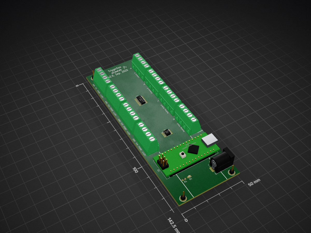
Triggerbox is an open-source printed circuit board by strawlab, from the strawlab/triggerbox repository on GitHub, published under the Apache-2.0 licence. It is a 2-layer board of 50 × 142.5 mm with 19 parts on 38 nets, routed with 202 tracks and 6 vias.
It is built around the SN74HC125D and MCP4822-E/P. Its parts include 9 connectors, 3 ICs, 1 resistor and 1 diode. It belongs with the AVR (ATmega, ATtiny) boards of this library.


Cameras trigger inputs are connected to pin D9 on an Arduino. (Optionally, a buffer amplifier can be used. See below for why this may be a good idea.) This is used to generate a digital pulse which triggers image acquisition on cameras. Furthermore, a host PC communicates with the Arduino to build a live model of the clocks on both systems and allows very precise (sub-millisecond) determination of the timing of trigger pulses from the Arduino. This allows precise timing information to be taken from the resulting acquired image frames.
The minimal required hardware is this:
If using the minimal hardware, you will need to connect pin D9 to the trigger inputs of your camera directly.
For additional robustness for multi-camera setups, particularly those that have
an opto-coupled trigger input which accordingly draws substantially more
current, you will want a buffer amplifier to trigger more cameras. In the
hardware_v1 and hardware_v2 directories are the PCB layouts, schematics, and enclosure of the triggerbox.
This firmware can be compiled and installed with the Arduino IDE or at the command line.
The file triggerbox.ino can be opened directly in the Arduino
IDE. Set your board to Arduino Nano
("Tools"->"Board"->"Arduino Nano"). Set your port ("Tools"->"Port") correctly,
which depends on your specific computer setup. Then click the "Upload" button.
To build this firmware for an Arduino Nano on Ubuntu linux, do the following steps.
Install the required software:
Intall Arduino CLI, then:
arduino-cli core update-index
arduino-cli core install arduino:avr
Compile the firmware
arduino-cli compile --fqbn arduino:avr:nanoUpload the firmware
# Note the port `/dev/ttyUSB0` may be different on your computer. In Windows,
# it will be something like `COM4`.
arduino-cli upload --port /dev/ttyUSB0 --fqbn arduino:avr:nanoRun the standalone demo program on your host PC.
dialout group (or
whichever group owns the device file - /dev/ttyUSB0 in the example below):
sudo adduser `whoami` dialout.The demo can be run like this:
cd braid-triggerbox-rs
# You may need to change the device path from `/dev/ttyUSB0` in this example.
# On Windows, this will be something like `COM4` instead of `/dev/ttyUSB0`.
cargo run -- --device /dev/ttyUSB0 --fps 100
If successful, the output will look like:
Requested 100 fps, using 100 fps
Connecting to trigger device ..
got new time model: None
.. connected.
got new time model: Some(ClockModel { gain: 0.009991053259000182, offset: 1642089273.653188, residuals: 0.00008373855939680652, n_measurements: 5 })
got new time model: Some(ClockModel { gain: 0.009990740683861077, offset: 1642089273.65347, residuals: 0.00008408054048913982, n_measurements: 6 })
got new time model: Some(ClockModel { gain: 0.009990941849537194, offset: 1642089273.6532729, residuals: 0.00008470585419217969, n_measurements: 7 })
got new time model: Some(ClockModel { gain: 0.0099910874851048, offset: 1642089273.6531227, residuals: 0.00008554253827242064, n_measurements: 8 })
got new time model: Some(ClockModel { gain: 0.009991202969104052, offset: 1642089273.652988, residuals: 0.0000863512614728279, n_measurements: 9 })
got new time model: Some(ClockModel { gain: 0.009991223458200693, offset: 1642089273.652963, residuals: 0.00008639545796995662, n_measurements: 10 })
got new time model: Some(ClockModel { gain: 0.009991292201448232, offset: 1642089273.6528616, residuals: 0.00008692377247143668, n_measurements: 11 })
got new time model: Some(ClockModel { gain: 0.009991496510338038, offset: 1642089273.6525416, residuals: 0.00009343214287582668, n_measurements: 12 })Apache 2.0 or MIT at your choice. See LICENSE-APACHE and LICENSE-MIT.
| Qty | Value | Footprint | References |
|---|---|---|---|
| 1 | 1 | 1pin | 1PIN 1 |
| 1 | 2 | 1pin | 1PIN 2 |
| 1 | 220 | Resistor_SMD:R_0603_1608Metric_Pad1.05x0.95mm_HandSolder | R1 |
| 1 | 3 | 1pin | 1PIN 3 |
| 1 | 4 | 1pin | 1PIN 4 |
| 1 | ARDUINO_NANO | Module:Arduino_Nano | U2 |
| 1 | Analog_In | TerminalBlock:TerminalBlock_bornier-4_P5.08mm | J8 |
| 1 | Analog_Out | TerminalBlock:TerminalBlock_bornier-4_P5.08mm | J7 |
| 1 | CamPW | Connector_BarrelJack:BarrelJack_Horizontal | J9 |
| 1 | LED | LED_SMD:LED_0603_1608Metric | D1 |
| 1 | LOGO | Straw_lab:stawlab_logo1 | G*** |
| 1 | MCP4822 | Package_SO:SOIC-8_3.9x4.9mm_P1.27mm | U3 |
| 1 | SN74HC125 | Package_SO:SOIC-14_3.9x8.7mm_P1.27mm | U1 |
| 1 | Trigger1 | TerminalBlock:TerminalBlock_bornier-4_P5.08mm | J1 |
| 1 | Trigger2 | TerminalBlock:TerminalBlock_bornier-4_P5.08mm | J2 |
| 1 | Trigger3 | TerminalBlock:TerminalBlock_bornier-4_P5.08mm | J3 |
| 1 | Trigger4 | TerminalBlock:TerminalBlock_bornier-4_P5.08mm | J4 |
| 1 | Trigger5 | TerminalBlock:TerminalBlock_bornier-4_P5.08mm | J5 |
| 1 | Trigger6 | TerminalBlock:TerminalBlock_bornier-4_P5.08mm | J6 |
It measures 50 × 142.5 mm and has 2 copper layers, 1.6 mm thick.
19 parts, built around the SN74HC125D and MCP4822-E/P. The full list of its parts is on this page, with links to each part's symbol and footprint where PCBKit's library has them.
From the strawlab/triggerbox repository on GitHub, at the commit this page was made from: the board is hardware_v2/circuit_board/triggerbox.kicad_pcb. PCBKit opens the board in the browser, with nothing to install.
Its repository publishes it under the Apache-2.0 licence: you may reuse it on that licence's terms (keep the author's notice, and for a copyleft licence share your changes alike).

fossasia/pslab-hardware
PSLab Hardware Design and Schematics https://pslab.io

matthewcieplak/super-sixteen
Code and schematics for the Super Sixteen Eurorack sequencer


sebastianbeyer/KOSMO_braids
This is a KOSMO (Look Mum No Computer) version of the Mutable instruments braids, based on the through-hole version done by sound-force.nl.

MiguelDeTrool/tarbleming
Arduino Nano based random looping sequencer Eurorack module