
4 layers99 × 53.3 mm
PSLab
fossasia/pslab-hardware
PSLab Hardware Design and Schematics https://pslab.io
199 parts1.7kApache-2.0

12-bit through-hole adaptation of Mutable Instruments Peaks
Apeks is an open-source printed circuit board by MiguelDeTrool, from the MiguelDeTrool/Apeks repository on GitHub, published under the MIT licence. It is a 2-layer board of 120 × 102.5 mm with 74 parts on 96 nets, routed with 343 tracks and 2 vias.
It is built around the MCP4822-E/P, LM7805 and B10K. Its parts include 26 resistors, 13 capacitors, 9 diodes, 9 connectors and 5 ICs.


Apeks is a DIY 12-bit through-hole adaptation of Mutable Instruments Peaks. Peaks was discontinued in 2017, but it's still pretty useful, and you can still see it in modern racks. For a starter system, it offers lots of functionality, so we made a version that's cheap and easy to fabricate, build, and modify.
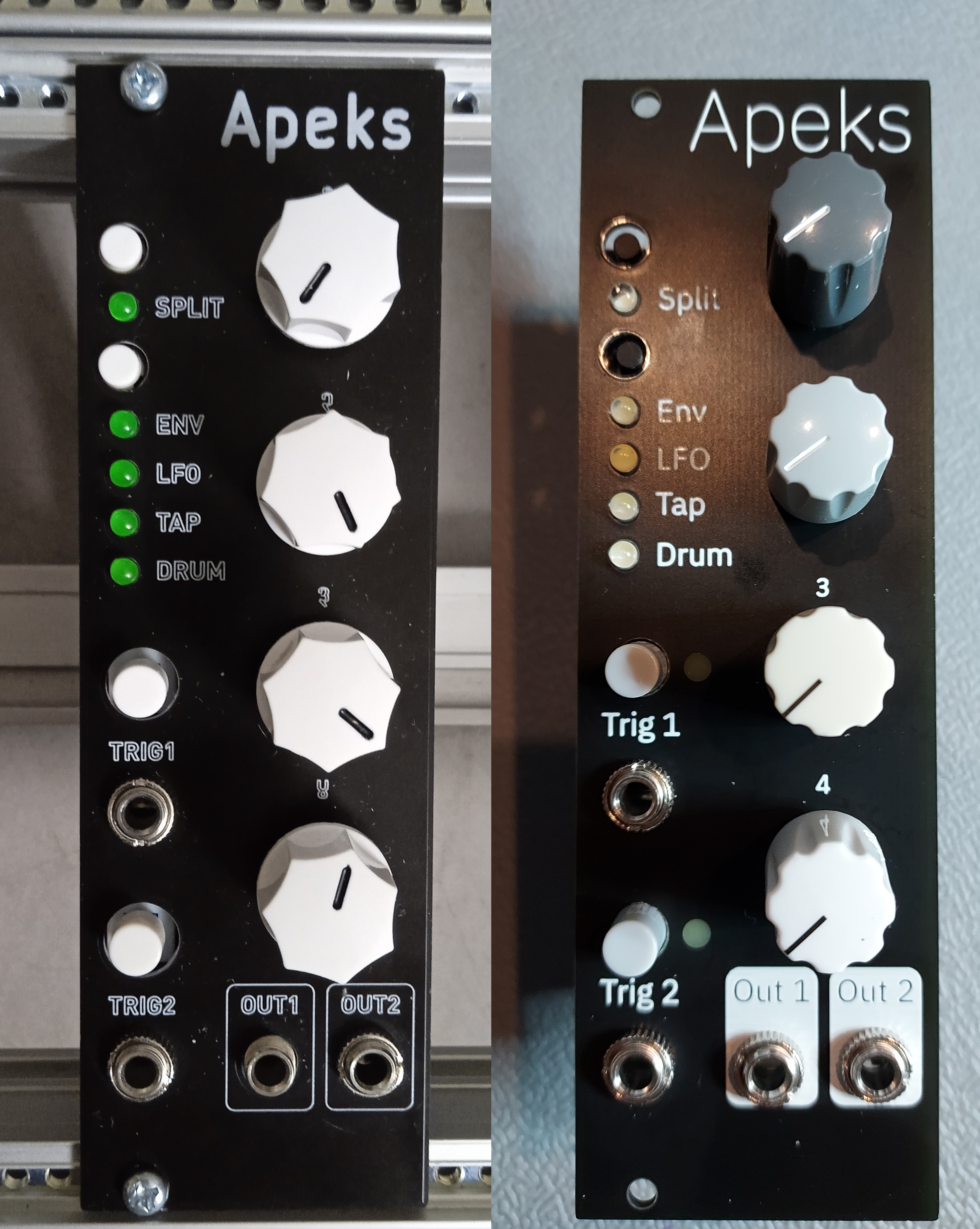
We saw what sound-force.nl did for Braids, and noticed Peaks used the same classic STM32 processor, so the same style of conversion could be done. Overall the conversion process was very similar to what Sound Force describes in their page about Braids: the layout is the same as it leaves space for THT components, the main PCB is shorter than 100mm, and the firmware only needs to have a few files changed (dac.h, dac.cc, lfo.h, and mini_sequencer.h).
The output stage needed to be modified slightly, as Peaks' output swing is 16V, which at 12 bits means the resolution would only be at almost 4mV. That's almost 5 cents at 1V/Oct, which is too much, as we could hear the steps in the output.
This version uses a 12 bit DAC, and the output op-amps scale the output to +/- 5V. This allows for a resolution of around 2.44mV, which we find acceptable for non-pitch related modulation.
For the DAC, the dac.h file is modified to bitshift the 16 bit values by 4 bits. The SPI output message use masks according to the MCP4822 write commands.
To bring the LFOs and mini-sequencers up to the maximum level (if not, they would be at around +/-3.125V), a couple of changes are needed. The lfo.h set_level arguments need to be set to 65535 instead of 40960, and in the output line of mini_sequencer.h, the same number needs to be changed.
The firmware is available as source and pre-compiled. We used a CP2102 and STM32CubeProg to program the chip (see images for a wiring diagram).
When you use the module for the first time, flash the bootloader and the main firmware. Then take care to calibrate it according to these instructions.
There are two panel versions. One uses 6mm caps for the trigger buttons, with LEDs that shine through the PCB beside them. The other has 8mm holes for the original illuminated buttons. Note: We've only tried our prototype panels for now, we haven't had these panels fabricated yet.
This version stays as close as possible to the original, but we'd be excited to see further modifications and improvements. We're working on a 64kb firmware (no easter egg and smaller bootloader), and a Dead Man's Catch adaptation.
But why not try to add CV inputs with attenuverters for the pots, make an SMD micro version that can be pre-fabbed, use an adapter board to use another DAC, see if you can do the same for Tides v1 etc...
We've included a BOM with links to Tayda, where you can source almost all the parts quite cheaply. The BOM includes some helpful notes about some components.
It's very hard to get ahold of boards with genuine STM32 chips right now. We haven't tested this with any other versions, like APM32, GD32, CH32 etc... but we can only assume that they will work too. Just be careful that the pinouts match!
This is a DIY project, with no instructions or build support. However, I can try to answer some questions you may have (if I have the time) at migueldetrool@protonmail.com.
Check out Quinie's blog and shop, where there are PCB and panels for sale.
If you get these boards or panels fabricated, please do contact me. These boards have been tested, but still, maybe I oversaw a problem, so it would be good to have confirmation that these work for others.
Thanks to sound-force.nl and matias-levy for inspiration, and Emilie Gillet for the original design and helpful forum posts.
| Qty | Value | Footprint | References |
|---|---|---|---|
| 9 | 2k | Resistor_THT:R_Axial_DIN0204_L3.6mm_D1.6mm_P7.62mm_Horizontal | R11, R13, R18, R19, R20, R21, R22, R23, R24 |
| 7 | LED | LED_THT:LED_D3.0mm | D3, D4, D5, D6, D7, D8, D9 |
| 6 | 39k | Resistor_THT:R_Axial_DIN0204_L3.6mm_D1.6mm_P7.62mm_Horizontal | R6, R7, R8, R9, R25, R26 |
| 4 | 100k | Resistor_THT:R_Axial_DIN0204_L3.6mm_D1.6mm_P7.62mm_Horizontal | R1, R3, R14, R15 |
| 4 | 220p | Capacitor_THT:C_Disc_D3.4mm_W2.1mm_P2.50mm | C2, C3, C4, C5 |
| 4 | B10k | Potentiometer_THT:Potentiometer_Alpha_RD901F-40-00D_Single_Vertical_CircularHoles | RV1, RV2, RV3, RV4 |
| 3 | 100n | Capacitor_THT:C_Disc_D3.4mm_W2.1mm_P2.50mm | C11, C12, C13 |
| 2 | 10k | Resistor_THT:R_Axial_DIN0204_L3.6mm_D1.6mm_P7.62mm_Horizontal | R2, R5 |
| 2 | 1N5817 | Diode_THT:D_DO-41_SOD81_P10.16mm_Horizontal | D1, D2 |
| 2 | 1k | Resistor_THT:R_Axial_DIN0204_L3.6mm_D1.6mm_P7.62mm_Horizontal | R16, R17 |
| 2 | 200k | Resistor_THT:R_Axial_DIN0204_L3.6mm_D1.6mm_P7.62mm_Horizontal | R10, R12 |
| 2 | 22uf | Capacitor_THT:CP_Radial_D5.0mm_P2.50mm | C6, C7 |
| 2 | 2N3904 | Package_TO_SOT_THT:TO-92_Wide | Q1, Q2 |
| 2 | 39p | Capacitor_THT:C_Disc_D3.4mm_W2.1mm_P2.50mm | C9, C10 |
| 2 | MountingHole | MountingHole:MountingHole_3.2mm_M3 | H1, H2 |
| 2 | SW_Push_Dual | Button_Switch_THT:SW_PUSH_6mm | SW1, SW2 |
| 1 | 0,33u | Capacitor_THT:CP_Radial_D5.0mm_P2.50mm | C8 |
| 1 | 0.47uf | Capacitor_THT:C_Disc_D3.4mm_W2.1mm_P2.50mm | C1 |
| 1 | 3.3k | Resistor_THT:R_Axial_DIN0204_L3.6mm_D1.6mm_P7.62mm_Horizontal | R4 |
| 1 | Bluepill | BluePill_breakouts:BluePill_STM32F103C | U1 |
| 1 | Conn_01x10 | Connector_PinSocket_2.54mm:PinSocket_1x10_P2.54mm_Vertical | J9 |
| 1 | Conn_01x10 | Connector_PinHeader_2.54mm:PinHeader_1x10_P2.54mm_Vertical | J7 |
| 1 | Conn_01x11 | Connector_PinHeader_2.54mm:PinHeader_1x11_P2.54mm_Vertical | J6 |
| 1 | Conn_01x11 | Connector_PinSocket_2.54mm:PinSocket_1x11_P2.54mm_Vertical | J8 |
| 1 | Eurorack Power | Connector_IDC:IDC-Header_2x05_P2.54mm_Vertical | J3 |
| 1 | LM4040LP-10 | Package_TO_SOT_THT:TO-92_Inline_Wide | U2 |
| 1 | LM7805 | Package_TO_SOT_THT:TO-220-3_Horizontal_TabDown | U5 |
| 1 | MCP4822 | Package_DIP:DIP-8_W7.62mm | U4 |
| 1 | SW_TRIG1 | Eurocad:LP4OA1PBCT | SW3 |
| 1 | SW_TRIG2 | Eurocad:LP4OA1PBCT | SW4 |
| 1 | TL074 | Package_DIP:DIP-14_W7.62mm_Socket_LongPads | U3 |
| 1 | in1 | Connector_Audio:Jack_3.5mm_QingPu_WQP-PJ398SM_Vertical_CircularHoles | J1 |
| 1 | in2 | Connector_Audio:Jack_3.5mm_QingPu_WQP-PJ398SM_Vertical_CircularHoles | J2 |
| 1 | out1 | Connector_Audio:Jack_3.5mm_QingPu_WQP-PJ398SM_Vertical_CircularHoles | J4 |
| 1 | out2 | Connector_Audio:Jack_3.5mm_QingPu_WQP-PJ398SM_Vertical_CircularHoles | J5 |
fossasia/pslab-hardware
PSLab Hardware Design and Schematics https://pslab.io

matthewcieplak/super-sixteen
Code and schematics for the Super Sixteen Eurorack sequencer


strawlab/triggerbox
camera triggering for synchronized multi-camera setups

sebastianbeyer/KOSMO_braids
This is a KOSMO (Look Mum No Computer) version of the Mutable instruments braids, based on the through-hole version done by sound-force.nl.

MiguelDeTrool/tarbleming
Arduino Nano based random looping sequencer Eurorack module

It measures 120 × 102.5 mm and has 2 copper layers, 1.6 mm thick.
74 parts, built around the MCP4822-E/P, LM7805 and B10K. The full list of its parts is on this page, with links to each part's symbol and footprint where PCBKit's library has them.
From the MiguelDeTrool/Apeks repository on GitHub, at the commit this page was made from: the board is hardware/pcb/Apeks.kicad_pcb and its schematic hardware/pcb/Apeks.kicad_sch. PCBKit opens the board in the browser, with nothing to install.
Its repository publishes it under the MIT licence: you may reuse it on that licence's terms (keep the author's notice, and for a copyleft licence share your changes alike).