2 layers82.1 × 82.1 mm
Uncut Gem
QuantumVillage/UncutGem
A prototype Full Stack fully Open Source NV Center Diamond Magnetometer
207 parts210AGPL-3.0

 stevenchadburrow/AcolyteHandPICd241
PIC24FJ based game console
HandPICd24 is an open-source printed circuit board by stevenchadburrow, from the stevenchadburrow/AcolyteHandPICd24 repository on GitHub, published under the GPL-3.0 licence. It is a 4-layer board of 100 × 100 mm with 112 parts on 287 nets, routed with 770 tracks and 40 vias.
It is built around the PIC24EP512GP204-E/ML and LM1117MP-3.3. Its parts include 16 resistors, 15 connectors, 11 capacitors, 10 switches and 2 ICs. It belongs with the retro computing and games boards and the PIC boards of this library.


Acolyte Hand PIC'd 24
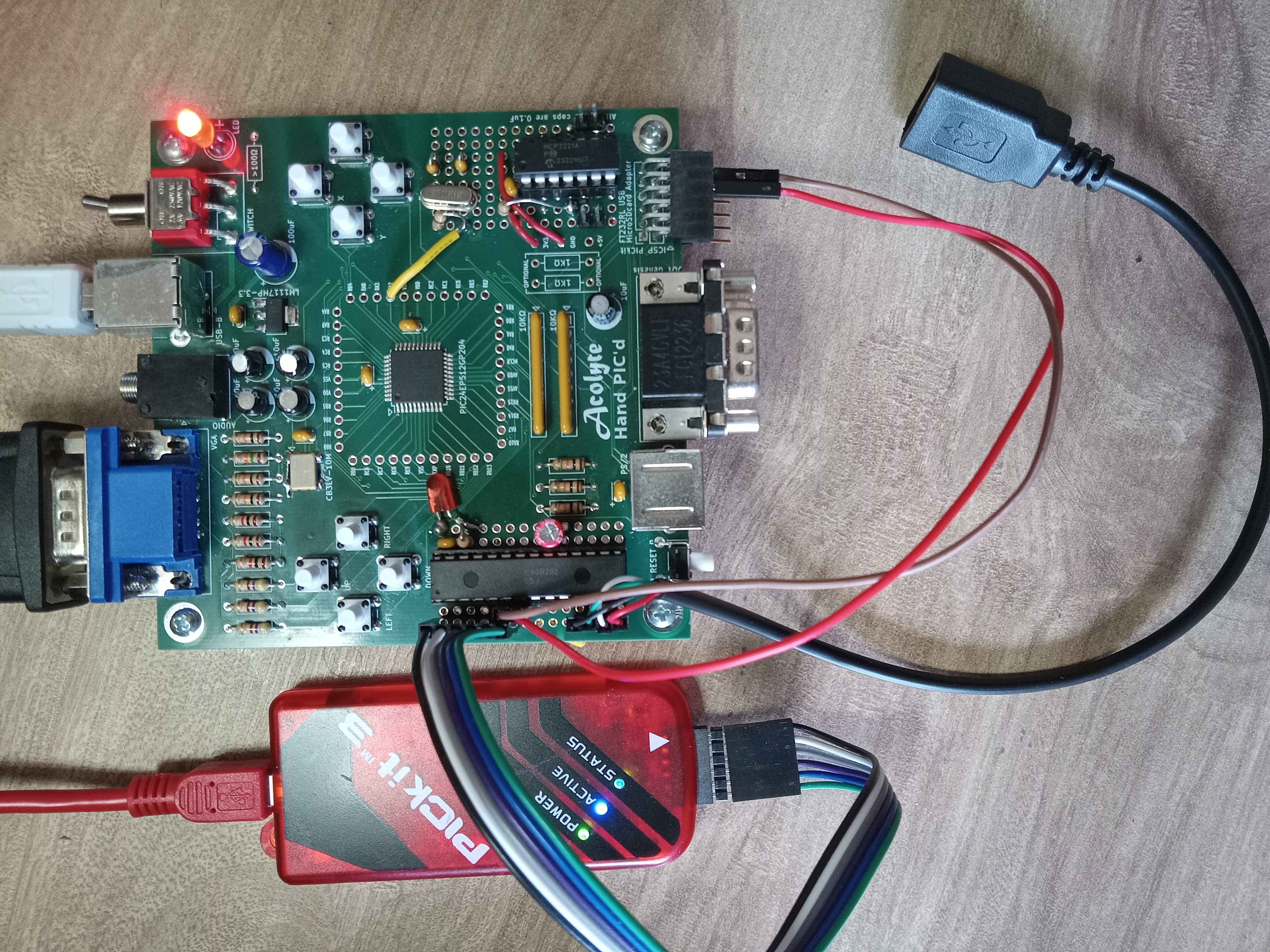
This is a single-chip retro-style computer using only the PIC24EP512GP204 microcontroller. Inspired by Voja Antonic's design found here: http://www.voja.rs/PROJECTS/GAME_HTM/1_intro.htm
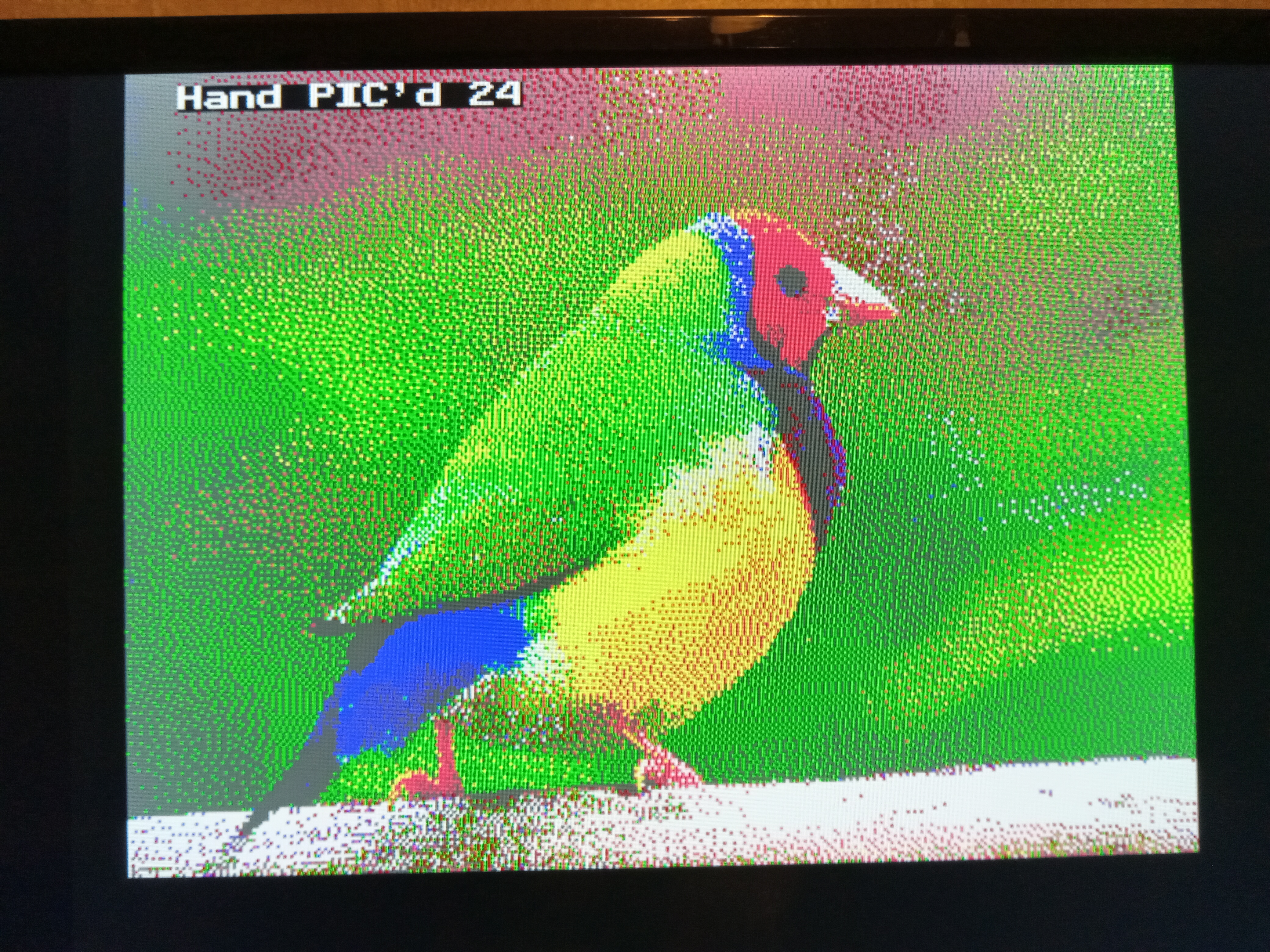
It is designed to output VGA display at 320x240 with 16 colors, and 2-voice audio square waves.
It is designed to receive input from a Sega Genesis controller, PS/2 Keyboard or Mouse, and 8 on-board buttons.
It is designed to use a MicroSD Card Adapter, and an FT232RL USB Adapter.
Programmed using MPLAB IDE X via a PICkit3.
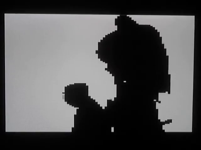
See my Youtube video for the Bad Apple demo. Either without audio or with audio.
Also see my 'Pokemon Clone', video link here. Although I am using the Tuxemon game art assets, this project is not the Tuxemon game, nor are the creators of the Tuxemon game in charge of this project. This project was simply inspired by the Tuxemon game.
Needed Changes:
*** LED silkscreen is confusing!!! ***
*** ICSP pins physically block the SDcard and FT232RL adapters!!! ***
*** Connected an MCP2221 to the USB connector for serial data transfer!!! ***
*** Tested with LCD, speaker, and with additional PIC24 chip for USB capability!!! ***
Updates:
Been working with the PIC24FJ128GB202 for USB capability. Using the MLA projects from Microchip, I was able to combine USB Host capabilities for using Keyboad, Mouse, and Mass Storage Device. See my .ZIP file for the entire project and all associated code. It is connected to this main board through an RX/TX UART pair, currently at 9600 baud.
A full 16-colors are available!
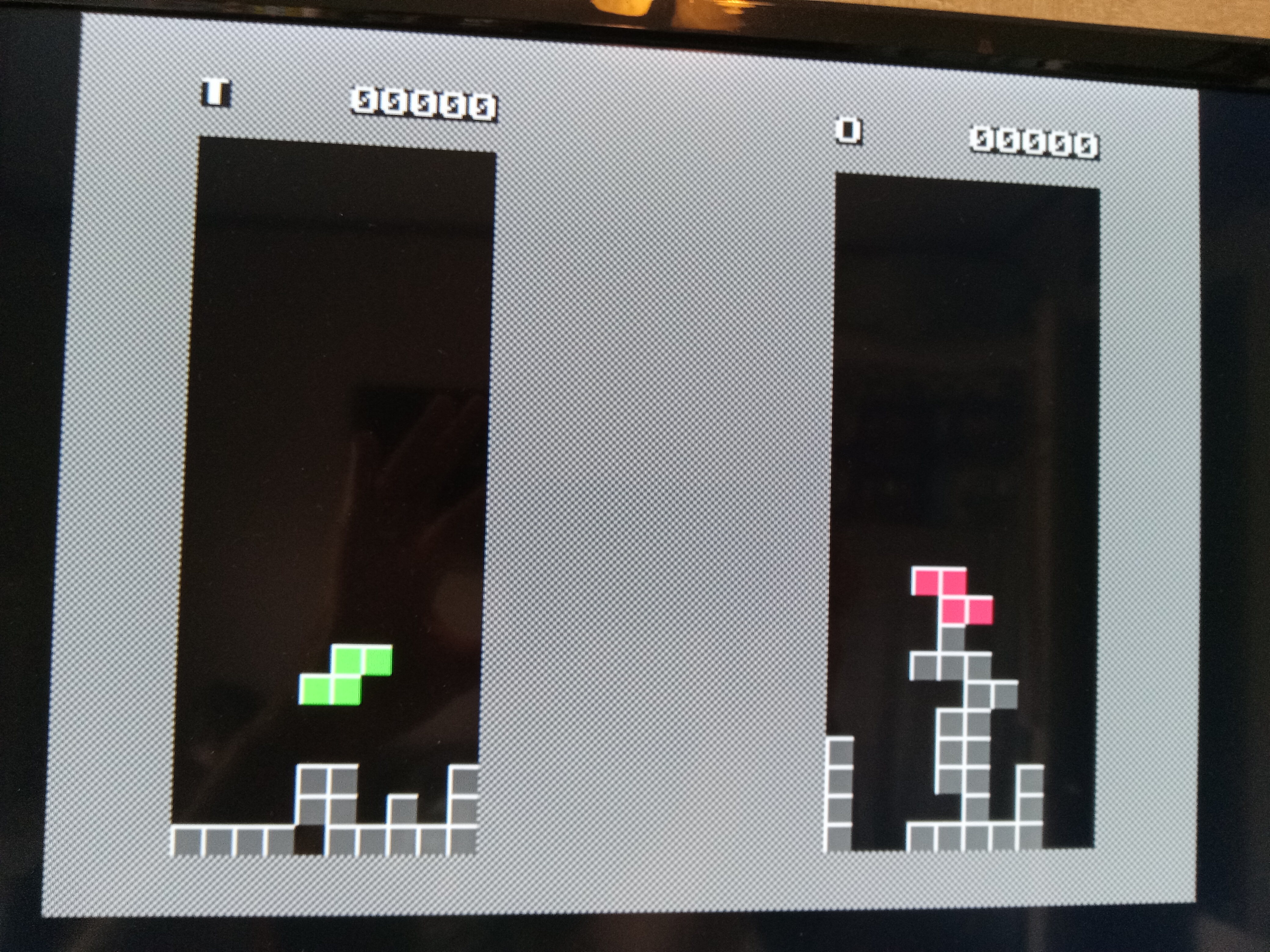
Tetra always seems to be the first game for any system.
It can even run Bad Apple!
| Qty | Value | Footprint | References |
|---|---|---|---|
| 47 | TestPoint | JustPIC:TestPointStdTHT | TP10, TP11, TP12, TP13, TP14, TP15, TP16, TP17, TP18, TP19, TP20, TP21, TP22, TP23, TP24, TP25 +31 |
| 16 | R_US | Resistor_THT:R_Axial_DIN0207_L6.3mm_D2.5mm_P10.16mm_Horizontal | R1, R2, R3, R4, R5, R6, R7, R8, R9, R10, R11, R12, R13, R14, R15, R17 |
| 8 | Conn_02x14_Odd_Even | HandPICd2:BLANK-PinHeader_2x14_P2.54mm_Vertical | J10, J11, J12, J13, J14, J15, J16, J17 |
| 8 | SW_Push | Button_Switch_THT:SW_PUSH_6mm_H5mm | SW2, SW4, SW5, SW6, SW7, SW8, SW9, SW10 |
| 5 | C_Polarized_Small_US | Capacitor_THT:CP_Radial_D6.3mm_P2.50mm | C1, C3, C4, C6, C8 |
| 5 | C_Small | Capacitor_THT:C_Disc_D3.0mm_W2.0mm_P2.50mm | C5, C7, C19, C25, C28 |
| 4 | TestPoint | JustPIC:ScrewHole-4-40 | TP1, TP2, TP3, TP4 |
| 2 | R_Network08_US | Resistor_THT:R_Array_SIP9 | RN1, RN2 |
| 1 | AudioJack3 | JustPIC:BIGJack_3.5mm_Ledino_KB3SPRS_Horizontal | J6 |
| 1 | CB3LV | Oscillator:Oscillator_SMD_EuroQuartz_XO91-4Pin_7.0x5.0mm | X1 |
| 1 | C_Polarized_US | Capacitor_THT:CP_Radial_D8.0mm_P2.50mm | C2 |
| 1 | Conn_01x06 | Connector_PinHeader_2.54mm:PinHeader_1x06_P2.54mm_Horizontal | J18 |
| 1 | Conn_02x06_Odd_Even | Connector_PinSocket_2.54mm:PinSocket_2x06_P2.54mm_Vertical | J1 |
| 1 | DE15_Receptacle_HighDensity | JustPIC:DSUB-15-HD_Female_Horizontal_P2.29x2.54mm_VGA | J5 |
| 1 | DE9_Plug | Connector_Dsub:DSUB-9_Male_Horizontal_P2.77x2.84mm_EdgePinOffset7.70mm_Housed_MountingHolesOffset9.12mm | J3 |
| 1 | LED | JustPIC:CustomLED | D1 |
| 1 | LM1117MP-3.3 | Package_TO_SOT_SMD:SOT-223-3_TabPin2 | U2 |
| 1 | LOGO | JustPIC:HandPickedTitle | G102 |
| 1 | LOGO | JustPIC:AcolyteTitle | G101 |
| 1 | LOGO | Library:Mystery | G103 |
| 1 | Mini-DIN-6 | JustPIC:PS2_Din6 | J2 |
| 1 | PIC24EP512GP204 | Package_QFP:TQFP-44_10x10mm_P0.8mm | U1 |
| 1 | SW_Push | Button_Switch_THT:SW_Tactile_SPST_Angled_PTS645Vx83-2LFS | SW1 |
| 1 | SW_SPDT | JustPIC:SPDT-100SP1T2B4M6QE | SW3 |
| 1 | USB_B | Connector_USB:USB_B_Lumberg_2411_02_Horizontal | J4 |
QuantumVillage/UncutGem
A prototype Full Stack fully Open Source NV Center Diamond Magnetometer

NYDEREK/LineFollower_GRUZIK2.0-light
GRUZIK2.0 is simple light construction made for "line follower light" competition

BG6LH/FT-81x-BT-DIGI-Adaptor
A PCB Design of Bluetooth DIGI Adaptor for Yaesu FT-817/818 Series Transceivers

shufps/vfd-night-projector-clock
The VFD Night Projector Clock is the first and only (at the moment and to my knowledge 😁) night projecting clock that uses a VFD display.


95lux/aware01
Aarebot is a dynamic realtime sampler built as a Eurorack module. At its core is a stereo tape-style engine with a hot-swapping record/playback buffer - this enables to record and play simultaneously.

porast1/suspension-telemetry
Suspension telemetry system for mountain bike or dirt bike

It measures 100 × 100 mm and has 4 copper layers, 1.6 mm thick.
112 parts, built around the PIC24EP512GP204-E/ML and LM1117MP-3.3. The full list of its parts is on this page, with links to each part's symbol and footprint where PCBKit's library has them.
From the stevenchadburrow/AcolyteHandPICd24 repository on GitHub, at the commit this page was made from: the board is HandPICd24.kicad_pcb and its schematic HandPICd24.kicad_sch. PCBKit opens the board in the browser, with nothing to install.
Its repository publishes it under the GPL-3.0 licence: you may reuse it on that licence's terms (keep the author's notice, and for a copyleft licence share your changes alike).