2 layers178 × 711 mm

 stevefarra/ec-stingy
A cheap, compact electrocardiogram
Ec stingy is an open-source printed circuit board by stevefarra, from the stevefarra/ec-stingy repository on GitHub, published under the MIT licence. It is a 2-layer board of 61 × 33.1 mm with 57 parts on 95 nets, routed with 469 tracks and 56 vias.
It is built around the STM32F334R8T6, CP2102N-A02-GQFN20R and PCM12SMTR. Its parts include 22 capacitors, 18 resistors, 4 connectors, 3 ICs and 2 diodes. It belongs with the STM32 boards of this library.


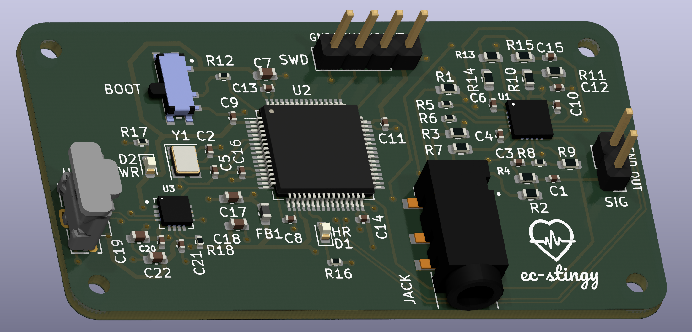
This directory includes several files with project metadata, but the key files are:
pcb.kicad_pro: KiCad 6 project file. Use this to properly load and open the schematic and layout files.
pcb.kicad_sch: The schematic file.
pcb.kicad_pcb: The layout file.
libraries/: Contains symbols, footprints, and 3D models for components used in the project that are included in the KiCad library.
manufacturing/: Contains a bill of materials, a component placement file, and gerber files required to get the board produced.
We heavily based the overall design and microcontroller layout on the KiCad 6 STM32 tutorial, with several notable additions:
We also added several peripherals to facilitate use and debugging:
The schematic ends up falling roughly into 5 sections:
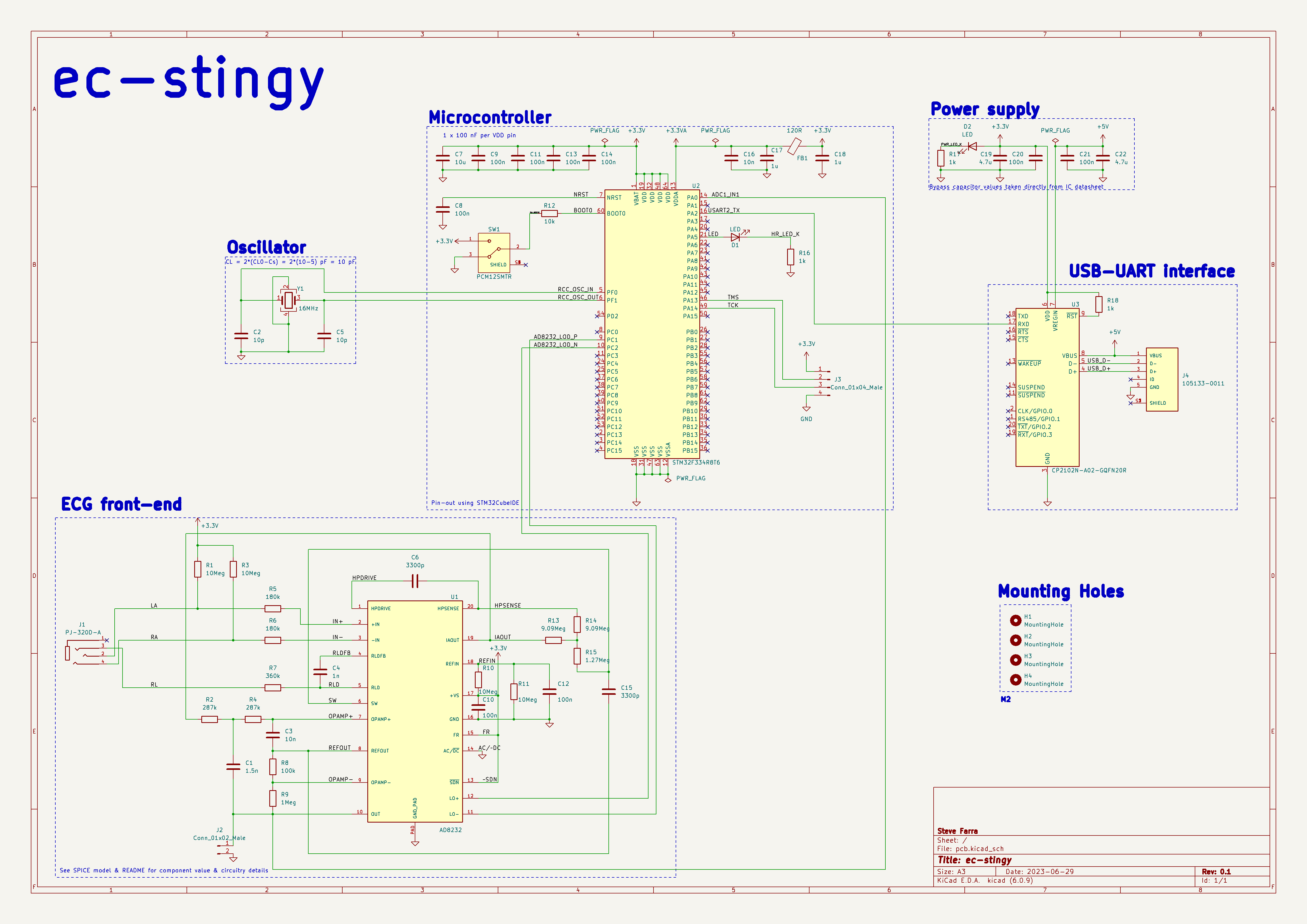
Before approaching the layout, we first consult PCB layout guidelines provided by the various ICs used. From the AD8232 datasheet:
Keep all of the connections between high impedance nodes as short as possible to avoid introducing additional noise and errors from corrupting the signal. To maintain high CMRR over frequency, keep the input traces symmetrical and length matched. Place safety and input bias resistors in the same position relative to each input. In addition, the use of a ground plane significantly improves the noise rejection of the system.
And from the STM32 datasheet:
Each power-supply pair (VDD/VSS, VDDA/VSSA etc..) must be decoupled with filtering ceramic capacitors as shown above. These capacitors must be placed as close as possible to or below the appropriate pins on the underside of the PCB, to ensure the good functionality of the device. The 10 nF capacitor must be ceramic (good quality) and it must be placed as close as possible to the chip.
With these principles in mind, a heavy draw of inspiration from the layout of the SparkFun AD8232 breakout, and a modest amount of trial-and-error, the resultant two-layer board layout came out like so:
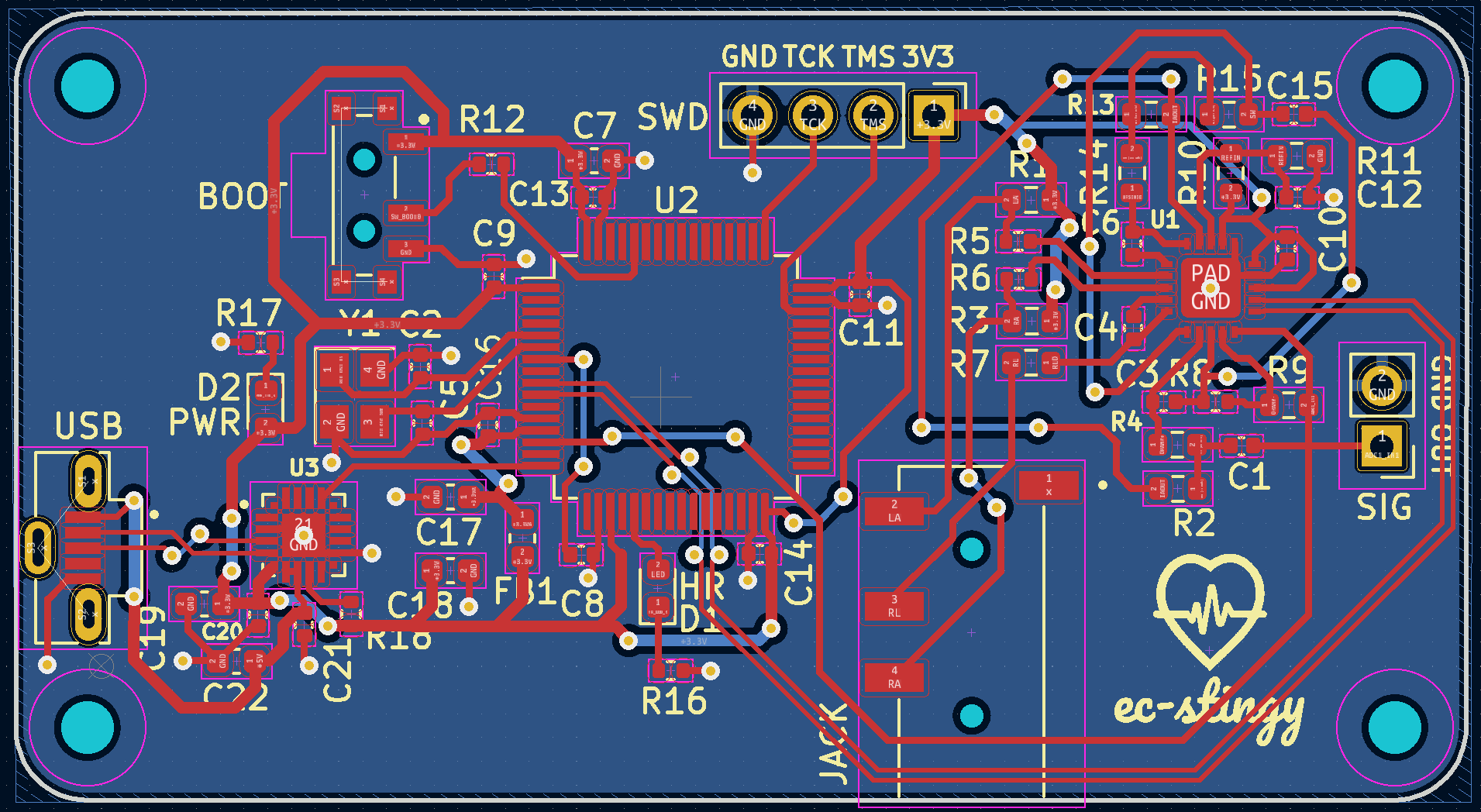
Time and effort were put into ensuring that the components chosen were economical and readily available to reduce the manufacturing cost as much as possible. Below is a breakdown of the per-board manufacturing costs at the time of writing this, ordering from JLCPCB (minimum quantity of 5):
| Category | Cost (CAD) |
|---|---|
| Passives | $0.50 |
| Connectors | $1.13 |
| ICs | $6.86 |
| Assembly | $3.07 |
Although it's difficult to directly compare this device to commercially-available products, the closest would be a Holter monitor like the Prince 180B1 from Heal Force which currently retails at $140 CAD. The total cost of our board comes to $11.56 CAD, which is roughly 9% of the market equivalent. Not bad!
Commission a board review: Despite passing KiCad's electrical and design rule checks, a third-party formal review could validate the schematic and layout. This review would also ensure adherence to best practices on differential trace length matching, passive component sizing, and decoupling capacitor layout, helping to prevent potential costly or time-consuming errors before manufacturing.
Add more safeguards: This device is far from being fully IEC 60601-compliant, but replacing the PC power supply with an external battery, adding TVS diodes to sensitive traces for ESD protection, and using an optocoupler to provide electrical isolation between the patient and the ECG would all increase the device's overall safety.
Compactify the layout: The board size comes in at roughly 61 mm by 33 mm, but there is still quite a bit of unused space which could be used for more peripherals or done away with altogether by rearranging components.
Design an enclosure: A hard casing with cutouts for peripheral access and LED viewing could enhance this project. The board already has mounting holes for fastening. KiCad's StepUp tool allows the 3D model above to be easily imported into FreeCAD and would come in handy here.
| Qty | Value | Footprint | References |
|---|---|---|---|
| 9 | 100n | Capacitor_SMD:C_0402_1005Metric | C8, C9, C10, C11, C12, C13, C14, C20, C21 |
| 4 | 10Meg | Resistor_SMD:R_0603_1608Metric | R1, R3, R10, R11 |
| 4 | MountingHole | MountingHole:MountingHole_2.2mm_M2 | H1, H2, H3, H4 |
| 3 | 1k | Resistor_SMD:R_0402_1005Metric | R16, R17, R18 |
| 2 | 10n | Capacitor_SMD:C_0402_1005Metric | C3, C16 |
| 2 | 10p | Capacitor_SMD:C_0402_1005Metric | C2, C5 |
| 2 | 180k | Resistor_SMD:R_0402_1005Metric | R5, R6 |
| 2 | 1u | Capacitor_SMD:C_0603_1608Metric | C17, C18 |
| 2 | 287k | Resistor_SMD:R_0603_1608Metric | R2, R4 |
| 2 | 3300p | Capacitor_SMD:C_0402_1005Metric | C6, C15 |
| 2 | 4.7u | Capacitor_SMD:C_0603_1608Metric | C19, C22 |
| 2 | 9.09Meg | Resistor_SMD:R_0603_1608Metric | R13, R14 |
| 2 | LED | LED_SMD:LED_0603_1608Metric | D1, D2 |
| 1 | 1.27Meg | Resistor_SMD:R_0603_1608Metric | R15 |
| 1 | 1.5n | Capacitor_SMD:C_0402_1005Metric | C1 |
| 1 | 100k | Resistor_SMD:R_0402_1005Metric | R8 |
| 1 | 105133-0011 | 105133-0011:MOLEX_105133-0011 | J4 |
| 1 | 10k | Resistor_SMD:R_0402_1005Metric | R12 |
| 1 | 10u | Capacitor_SMD:C_0603_1608Metric | C7 |
| 1 | 120R | Inductor_SMD:L_0603_1608Metric | FB1 |
| 1 | 16MHz | Crystal:Crystal_SMD_3225-4Pin_3.2x2.5mm | Y1 |
| 1 | 1Meg | Resistor_SMD:R_0603_1608Metric | R9 |
| 1 | 1n | Capacitor_SMD:C_0402_1005Metric | C4 |
| 1 | 360k | Resistor_SMD:R_0603_1608Metric | R7 |
| 1 | AD8232 | AD8232:LFCSP_20 | U1 |
| 1 | CP2102N-A02-GQFN20R | CP2102N-A02-GQFN20R:SILABS_CP2102N-A02-GQFN20R | U3 |
| 1 | Conn_01x02_Male | Connector_PinHeader_2.54mm:PinHeader_1x02_P2.54mm_Vertical | J2 |
| 1 | Conn_01x04_Male | Connector_PinHeader_2.54mm:PinHeader_1x04_P2.54mm_Vertical | J3 |
| 1 | LOGO | LOGO | G*** |
| 1 | PCM12SMTR | PCM12SMTR:SW_PCM12SMTR | SW1 |
| 1 | PJ-320D-A | PJ-320D-A:HRO_PJ-320D-A | J1 |
| 1 | STM32F334R8T6 | Package_QFP:LQFP-64_10x10mm_P0.5mm | U2 |
It measures 61 × 33.1 mm and has 2 copper layers, 1.6 mm thick.
57 parts, built around the STM32F334R8T6, CP2102N-A02-GQFN20R and PCM12SMTR. The full list of its parts is on this page, with links to each part's symbol and footprint where PCBKit's library has them.
From the stevefarra/ec-stingy repository on GitHub, at the commit this page was made from: the board is pcb/pcb.kicad_pcb and its schematic pcb/pcb.kicad_sch. PCBKit opens the board in the browser, with nothing to install.
Its repository publishes it under the MIT licence: you may reuse it on that licence's terms (keep the author's notice, and for a copyleft licence share your changes alike).


MF-Room/mseq_pcb
KiCad 10 hardware design for MSeq embedded, the microcontroller implementation of the MSeq MIDI sequencer.

Queens-Rocket-Engineering-Team/av-power
QRET Avionics PCBs and firmware for delivering power to SRAD PCBs

ashfaque-ur-rahman/ESP32-Multi-Sensor-PCB
ESP32-based multi-sensor PCB with temperature/humidity, light, and microphone sensors — 4 layer Board — KiCad design based on Tech Explorations tutorial

krishnaverma24/ESP32-4Layer-PCB-Design
This project is a custom-designed PCB integrating the ESP32 microcontroller with multiple sensors on a single board. The goal was to create a compact, versatile hardware platform for IoT and embedded system experiments.

