2 layers65 × 56 mm
 stasiselectronics/MicroBBPS14
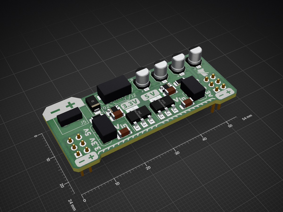
Small breadboard power supply that offers MicroUSB connector for 5V power, a screw terminal for max 20v DC power. Select between 5V, 3.3V or Vin for each power rail.
MicroBBPS is an open-source printed circuit board by stasiselectronics, from the stasiselectronics/MicroBBPS repository on GitHub. It is a 2-layer board of 54 × 24 mm with 23 parts on 12 nets, routed with 60 tracks and 10 vias.
Its parts include 8 capacitors, 6 connectors, 3 diodes, 2 resistors and 2 ICs. It belongs with the power boards of this library.

A small, Micro USB connected power supply designed to fit onto the power rails of a solderless breadboard.
For each side, you can select between 3.3 & 5.0 Volt linear regulators, or the input voltage at the screw terminal.
The integrated version adds 26 breadboard rows and 2 continuous power rails. So you can turn those prototypes into something more permanent with an easy microUSB power connector.
If you would like to read more about how the design works and see some of the technical information, be sure to check out the documentation site that accompanies this project.
This site is hosted on Github Pages, a great way to deploy your own static website using jekyll. It uses the wonderful theme Minimal Mistakes by Michael Rose.
Learn more about github pages.
This open source hardware project is developed using KiCAD and inkscape. It exists as a schematic and pcb design, with supporting files to create the necesarry output files for Printed Circuit Board fabrication.
Assemblies and Parts Kits are still available to purchase on Tindie, however current stock is starting to run low.
The PCBA is currently at Revision A02. The tag for this release contians all the design files as they were when fabrication files were generated.
If you would like to keep up to date with this project, be sure to check out my instagram
After incorporating the design changes from the first revision, the second revision came out great!
There are still a few details to try and adjust for any future fabrication.
Some of the major changes between on A02 from A01 are
Here are some photos of the first board revision


| Qty | Value | Footprint | References |
|---|---|---|---|
| 4 | 220nF 50V | Capacitor_SMD:C_1206_3216Metric_Pad1.33x1.80mm_HandSolder | C1, C2, C3, C4 |
| 2 | 10µF 16V | Capacitor_SMD:CP_Elec_4x5.4 | C5, C7 |
| 2 | 3PoleHeaderSwitch | MicroBBPS:3PoleHeaderSwitch | J8, J9 |
| 2 | 47µF 10V | Capacitor_SMD:CP_Elec_4x5.4 | C6, C8 |
| 2 | Conn_02x03 | Connector_PinHeader_2.54mm:PinHeader_2x03_P2.54mm_Vertical | J3, J4 |
| 2 | LED | Diode_SMD:D_1206_3216Metric_Pad1.42x1.75mm_HandSolder | D1, D3 |
| 1 | 0R | Resistor_SMD:R_1206_3216Metric_Pad1.30x1.75mm_HandSolder | R2 |
| 1 | 56R 0.25W | Resistor_SMD:R_1206_3216Metric_Pad1.30x1.75mm_HandSolder | R1 |
| 1 | Conn_01x02 | MicroBBPS:WJ124-3.81-2P | J5 |
| 1 | D | Diode_SMD:D_SMA | D2 |
| 1 | LOGO | MicroBBPS:artwork-bottom | G*** |
| 1 | LOGO | MicroBBPS:artwork-top | G*** |
| 1 | NCP1117ST33T3G | Package_TO_SOT_SMD:SOT-223-3_TabPin2 | U3 |
| 1 | NCP1117ST50T3G | Package_TO_SOT_SMD:SOT-223-3_TabPin2 | U1 |
| 1 | USB_B_Micro | MicroBBPS:U-F-M5DD-Y-L | J2 |
It measures 54 × 24 mm and has 2 copper layers, 1.6 mm thick.
23 parts. The full list of its parts is on this page, with links to each part's symbol and footprint where PCBKit's library has them.
From the stasiselectronics/MicroBBPS repository on GitHub, at the commit this page was made from: the board is Hardware Files/MicroBBPS.kicad_pcb. PCBKit opens the board in the browser, with nothing to install.
Its repository states no licence, so its author keeps all rights: ask stasiselectronics before reusing the design.

google/mozc-devices
Circuit diagrams and firmware source code for Gboard DIY keyboards


Duet3D/Duet-2-Hardware
The KiCAD source for the Duet 3d printer controller see www.duet3d.com