4 layers90 × 153 mm
Blackpants
o7-machinehum/Blackpants
Open blackpants.kicadpro for the active A523 schematic and PCB. It replaces the A33 hierarchy and uses AXP717C + AXP323 with 2GB LPDDR4.
139 parts189MIT
 stanislawkrowicki/put-ask1
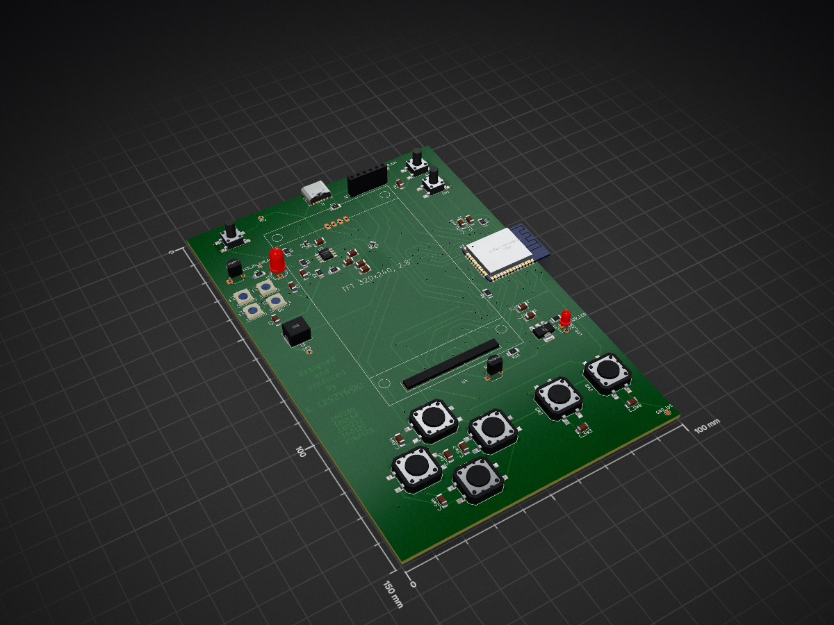
Portable and pocket size console, able to load games from external sd card. Possibility of on-line gameplay via Wi-Fi. Custom PCB board, self-made using CNC milling and UV solder mask paint; 3D printed case.
PCB Console is an open-source printed circuit board by stanislawkrowicki, from the stanislawkrowicki/put-ask repository on GitHub. It is a 2-layer board of 100 × 150 mm with 62 parts on 61 nets, routed with 633 tracks and 92 vias.
It is built around the ESP32-WROOM-32, IP5306 and WS2812B, with the 1N5819WS among its other parts. Its parts include 10 resistors, 9 switches, 8 capacitors, 7 diodes and 4 ICs. It belongs with the ESP32 boards of this library.


Portable GameBoy style console. Based on ESP32 microprocessor, 2.8" TFT display, WiFi
Portable and pocket size console, able to load games from external sd card. Possibility of on-line gameplay via Wi-Fi. Custom PCB board, self-made using CNC milling and UV solder mask paint; 3D printed case.
The PCB was designed to be produced using a double-sided FR4 PCB blank. Unfortunately, due to the process, every via had to be soldered using copper wire.
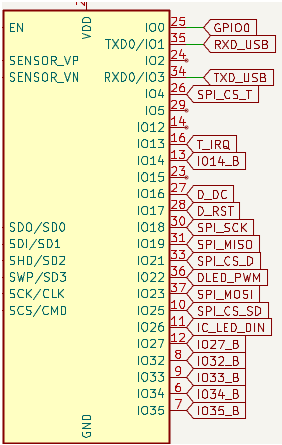
| Button | Switch id | GPIO |
|---|---|---|
| Right Button | SW_7 | IO35 |
| Left Button | SW_5 | IO27 |
| Up Button | SW_4 | IO33 |
| Down Button | SW_6 | IO34 |
| A Button | SW_8 | IO14 |
| B Button | SW_3 | IO32 |
| Touch Signal | Description | GPIO |
|---|---|---|
| MISO | Master In Slave Out | IO19 |
| MOSI | Master Out Slave In | IO23 |
| CLK | Clock | IO18 |
| CS_T | Chip Select | IO4 |
| T_IRQ | Interrupt Handling | IO13 |
| Display Signal | GPIO | Description |
|---|---|---|
| SPI_CS | IO21 | Display Chip Select |
| SPI_MOSI | IO23 | Master Out Slave In (data) |
| SPI_MISO | IO19 | Master In Slave Out (data) |
| SPI_CLK | IO18 | Clock signal |
| D_DC | IO16 | Data/Command control |
| D_RST | IO17 | Display reset signal |
| D_LED | IO22 | Display backlight control |
| SD Signal | GPIO | Description |
|---|---|---|
| SD_CS | IO25 | Chip Select karty SD |
| SD_CLK | IO18 | Clock signal |
| SD_MISO | IO19 | Master In Slave Out (data) |
| SD_MOSI | IO23 | Master Out Slave In (data) |
| 2x2 LED signal | GPIO | Description |
|---|---|---|
| LED_DIN | IO26 | Data in |
| SPI Signal | GPIO |
|---|---|
| MISO | IO19 |
| MOSI | IO23 |
| CLK | IO18 |
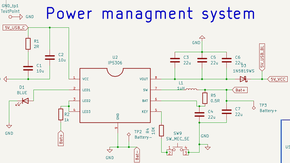
The console can be powered remotely using, for example, a 18650 Li-ion battery. Plugging the console into external power through USB-C will power the device and charge the battery. The IP5306 is used according to the typical application from the datasheet. We used a one-LED configuration and skipped the KEY_LED (D5 on the datasheet).
Description of how to use the project, e.g., how to start it, available modes, etc.
The PCB has been mostly successfully produced. We will leave a few notes describing our conclusions about what went wrong and what met or exceeded our expectations.
Power Management Unit Failure: To be honest, I still don’t know exactly what went wrong. The design followed the datasheet, but the IC consistently failed, producing enough heat to desolder itself. After several attempts and considering the project deadline, I abandoned the idea of a remote power supply. If I were to do this again, I’d design a separate board dedicated solely to power management.
Input-Only Pins (IO35, IO34): These pins lack internal pull-up resistors, and I neglected to include external ones in the design.
WS2812 Segment Issue: This one’s due to a simple oversight: the collector of the Q1 transistor isn’t pulled up to 5V, which prevents proper operation of the LED segment.
USB-C Port Soldering Difficulty: The mounting pads for the USB-C connector are too small, making the socket difficult to solder reliably. Larger pads would have made assembly easier.
| Qty | Value | Footprint | References |
|---|---|---|---|
| 6 | 100n | Capacitor_SMD:C_1206_3216Metric_Pad1.33x1.80mm_HandSolder | C_SW3, C_SW4, C_SW5, C_SW6, C_SW7, C_SW8 |
| 6 | SW_MEC_5E | Library:SW_Push_12x12_aliexpress | SW3, SW4, SW5, SW6, SW7, SW8 |
| 5 | 22u | Capacitor_SMD:C_1206_3216Metric_Pad1.33x1.80mm_HandSolder | C3, C4, C5, C6, C7 |
| 4 | WS2812B | LED_SMD:LED_WS2812B_PLCC4_5.0x5.0mm_P3.2mm | D4, D5, D6, D7 |
| 3 | 100nF | Capacitor_SMD:C_1206_3216Metric_Pad1.33x1.80mm_HandSolder | C_LDO_in1, C_LDO_out2, C8 |
| 3 | 1k | Resistor_SMD:R_1206_3216Metric_Pad1.30x1.75mm_HandSolder | R2, R6, R11 |
| 2 | 10k | Resistor_SMD:R_1206_3216Metric_Pad1.30x1.75mm_HandSolder | R8, R9 |
| 2 | 10u | Capacitor_SMD:C_1206_3216Metric_Pad1.33x1.80mm_HandSolder | C1, C2 |
| 2 | 10uF | Capacitor_SMD:C_1206_3216Metric_Pad1.33x1.80mm_HandSolder | C_LDO_in2, C_LDO_out1 |
| 2 | 1N5819WS | Diode_SMD:D_0805_2012Metric_Pad1.15x1.40mm_HandSolder | D2, D3 |
| 2 | 2N3904 | Package_TO_SOT_THT:TO-92_Wide | Q1, Q2 |
| 2 | SW_MEC_5E | components_lib:SW_TS04-66-95-BK-100-SMT | SW1, SW9 |
| 2 | TestPoint | TestPoint:TestPoint_Pad_D1.0mm | DTR_USB_tp1, LED_5V_DIN_tp1 |
| 1 | 0.5R | Resistor_SMD:R_1206_3216Metric_Pad1.30x1.75mm_HandSolder | R5 |
| 1 | 100uF | Capacitor_SMD:C_1206_3216Metric_Pad1.33x1.80mm_HandSolder | C9 |
| 1 | 10K | Resistor_SMD:R_1206_3216Metric_Pad1.30x1.75mm_HandSolder | R4 |
| 1 | 1uH | Inductor_SMD:L_Chilisin_BMRB00060650 | L1 |
| 1 | 200 | Resistor_SMD:R_1206_3216Metric_Pad1.30x1.75mm_HandSolder | LDO_33V_LEDR1 |
| 1 | 2R | Resistor_SMD:R_1206_3216Metric_Pad1.30x1.75mm_HandSolder | R1 |
| 1 | 330 | Resistor_SMD:R_1206_3216Metric_Pad1.30x1.75mm_HandSolder | R7 |
| 1 | 5.1k | Resistor_SMD:R_1206_3216Metric_Pad1.30x1.75mm_HandSolder | R3 |
| 1 | BLUE | LED_THT:LED_D5.0mm | D1 |
| 1 | Battery+ | TestPoint:TestPoint_THTPad_D1.5mm_Drill0.7mm | TP3 |
| 1 | Battery- | TestPoint:TestPoint_THTPad_D1.5mm_Drill0.7mm | TP2 |
| 1 | CP2102 module | Connector_PinSocket_2.54mm:PinSocket_1x06_P2.54mm_Vertical | J2 |
| 1 | ESP32-WROOM-32 | RF_Module:ESP32-WROOM-32 | U3 |
| 1 | GREEN | LED_THT:LED_D3.0mm | LDO_33V_LED1 |
| 1 | IP5306 | components_lib:SOIC9P127_490X600X170L84X42T330X241N | U2 |
| 1 | LD1117S33TR_SOT223 | Package_TO_SOT_SMD:SOT-223-3_TabPin2 | U1 |
| 1 | LOGO | LOGO | G*** |
| 1 | SW_MEC_5E | TS04-66-95-BK-100-SMT:SW_TS04-66-95-BK-100-SMT | SW2 |
| 1 | TestPoint | TestPoint:TestPoint_Pad_D1.5mm | GND_tp1 |
| 1 | USB_C_Receptacle_PowerOnly_6P | Connector_USB:USB_C_Receptacle_GCT_USB4125-xx-x-0190_6P_TopMnt_Horizontal | J1 |
| 1 | ~ | components_lib:TFT ILI9341 | U4 |
It measures 100 × 150 mm and has 2 copper layers, 1.6 mm thick.
62 parts, built around the ESP32-WROOM-32, IP5306, WS2812B and 1N5819WS. The full list of its parts is on this page, with links to each part's symbol and footprint where PCBKit's library has them.
From the stanislawkrowicki/put-ask repository on GitHub, at the commit this page was made from: the board is hardware/PCB_Console/PCB_Console.kicad_pcb and its schematic hardware/PCB_Console/PCB_Console.kicad_sch. PCBKit opens the board in the browser, with nothing to install.
Its repository states no licence, so its author keeps all rights: ask stanislawkrowicki before reusing the design.
o7-machinehum/Blackpants
Open blackpants.kicadpro for the active A523 schematic and PCB. It replaces the A33 hierarchy and uses AXP717C + AXP323 with 2GB LPDDR4.

klaus-liebler/self-balancing_robot
hardware and software for a super cheap self balancing robot


BitDogLab/BitDogLab
Open-source educational hardware for embedded systems, programming, electronics, and physical computing.

sneakylizard123-4/ESP32-S3_Module
This is a small, self-contained development board built around the ESP32-S3-WROOM-1U. The idea is a go-to prototyping board: drop in a LiPo, plug in USB-C, and you have a programmable ESP32-S3 with WiFi/BLE/Zigbee, a…


Capibator/hardware
deals with research material on hardware, schematic, pcb design and bom etc.