2 layers165.1 × 110 mm
 Capibator/hardware
deals with research material on hardware, schematic, pcb design and bom etc.
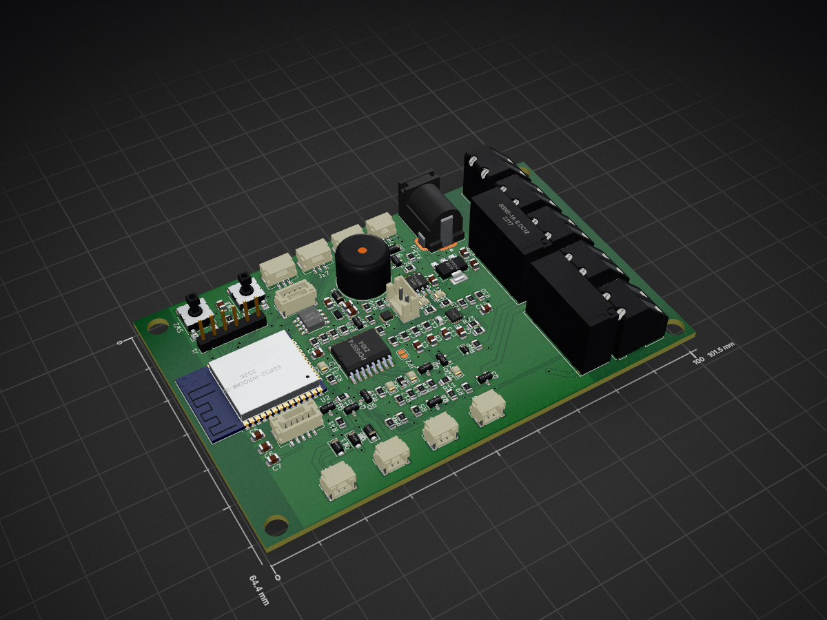
Capibator PCB is an open-source printed circuit board by Capibator, from the Capibator/hardware repository on GitHub. It is a 2-layer board of 101.5 × 64.4 mm with 108 parts on 89 nets, routed with 868 tracks and 107 vias.
It is built around the ESP32-WROOM-32, PCF8574T and TPS63070RNMR, with the AMS1117-5.0, DS1307+ and TP4056 among its other parts. Its parts include 33 resistors, 20 capacitors, 18 connectors, 13 diodes and 9 transistors. It belongs with the ESP32 boards of this library.


made with Kicad, 2 layers, lots of vias :D
This is how it looks as of right now.
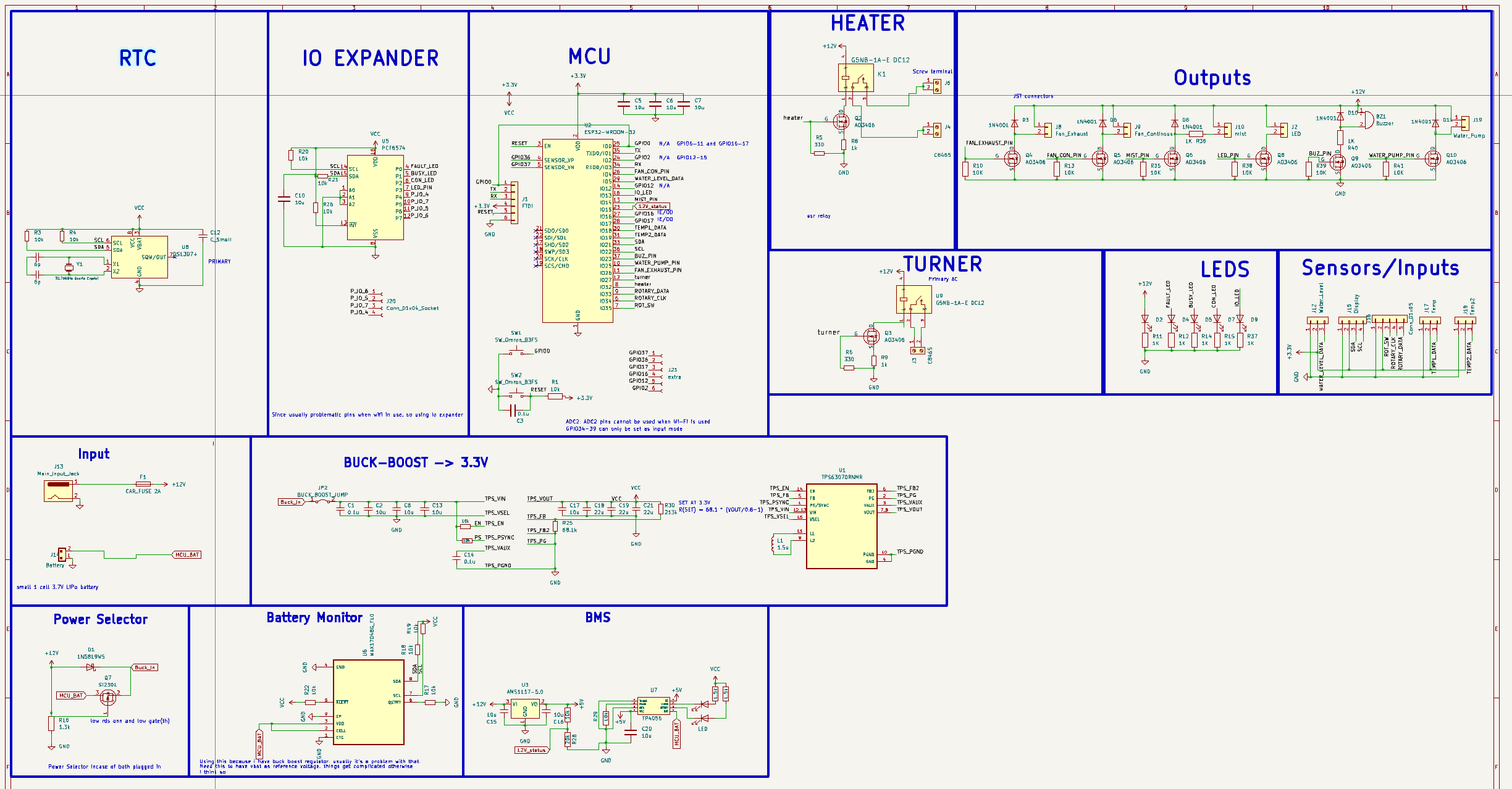 PCB
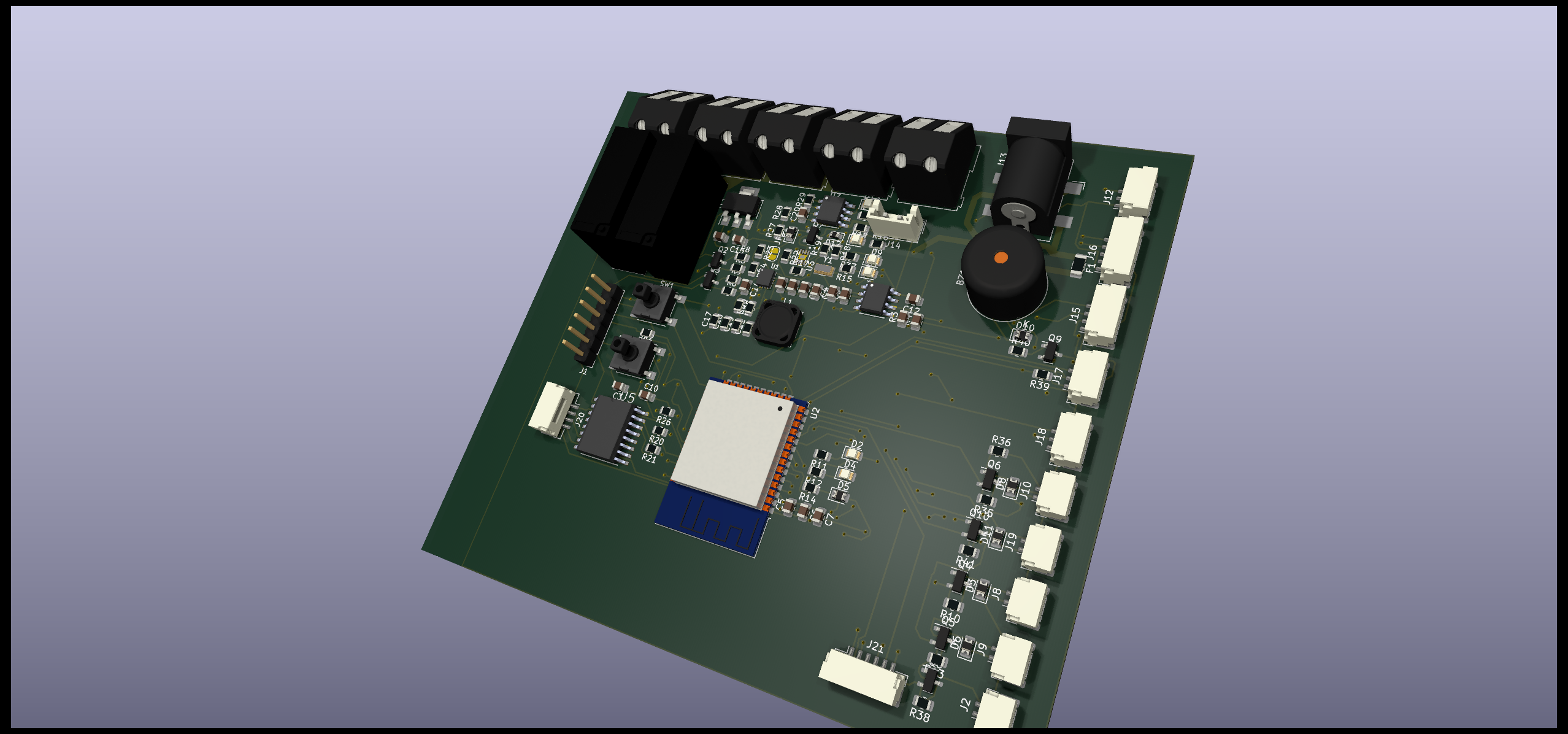
Better placement, hopefully this is better.
AC in one end and sensitive logic on the other.
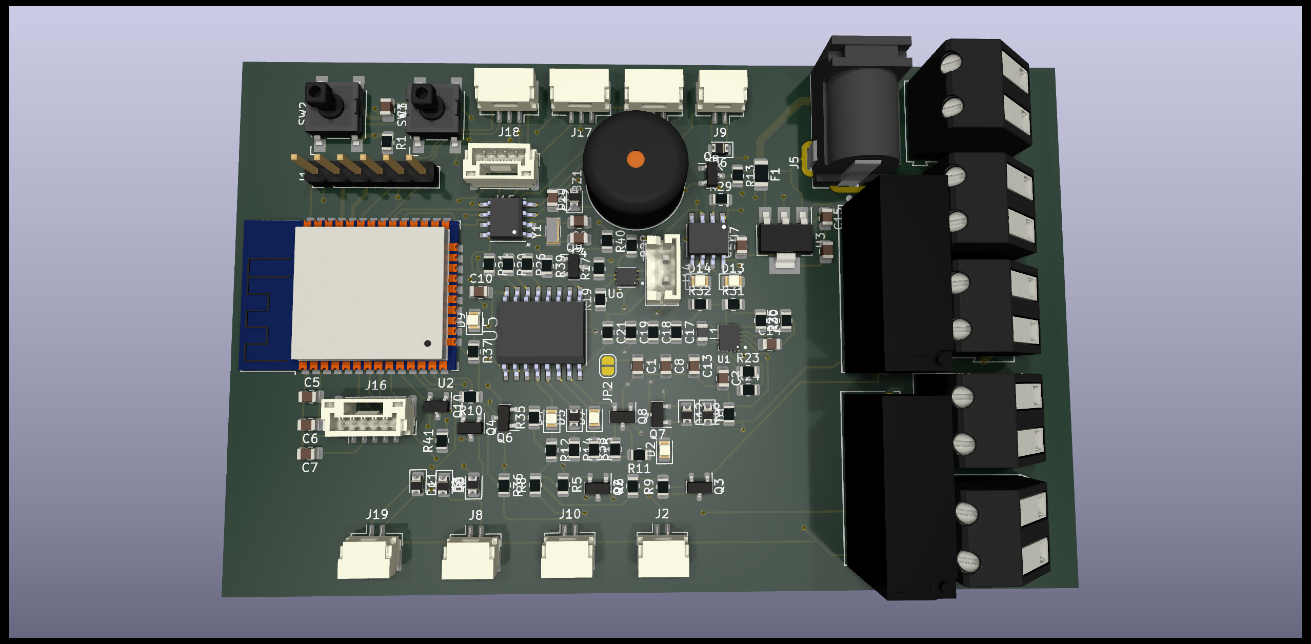
size 101.5mm x 61.4mm
| Qty | Value | Footprint | References |
|---|---|---|---|
| 11 | 10u | Capacitor_SMD:C_0805_2012Metric | C2, C5, C6, C7, C8, C10, C12, C13, C15, C16, C20 |
| 10 | 10k | Resistor_SMD:R_0805_2012Metric | R1, R17, R19, R20, R21, R22, R23, R24, R26, R29 |
| 8 | AO3406 | Package_TO_SOT_SMD:SOT-23 | Q2, Q3, Q4, Q5, Q6, Q8, Q9, Q10 |
| 7 | 100 | Resistor_SMD:R_0805_2012Metric | R11, R12, R14, R15, R31, R32, R37 |
| 6 | 10K | Resistor_SMD:R_0805_2012Metric | R10, R13, R35, R38, R39, R41 |
| 5 | 1N4001 | Diode_SMD:D_SOD-123F | D3, D6, D8, D10, D11 |
| 5 | C8465 | TerminalBlock:TerminalBlock_Altech_AK300-2_P5.00mm | J3, J4, J5, J6, J7 |
| 3 | 0.1u | Capacitor_SMD:C_0805_2012Metric | C1, C3, C14 |
| 3 | 22u | Resistor_SMD:R_0805_2012Metric | C18, C19, C21 |
| 3 | LED | LED_SMD:LED_0805_2012Metric | D9, D13, D14 |
| 2 | 1K | Resistor_SMD:R_0805_2012Metric | R36, R40 |
| 2 | 1k | Resistor_SMD:R_0805_2012Metric | R8, R9 |
| 2 | 330 | Resistor_SMD:R_0805_2012Metric | R5, R6 |
| 2 | 6p | Capacitor_SMD:C_0805_2012Metric | C4, C9 |
| 2 | G5NB-1A-E DC12 | G5NB-1A-E_DC12:RELAY_G5NB-1A_DC5_OMR | K1, U9 |
| 2 | SW_Omron_B3FS | Button_Switch_SMD:SW_SPST_Omron_B3FS-100xP | SW1, SW2 |
| 1 | 1.3k | Resistor_SMD:R_0805_2012Metric | R16 |
| 1 | 1.5u | Inductor_SMD:L_Murata_LQH2MCNxxxx02_2.0x1.6mm | L1 |
| 1 | 10u | Resistor_SMD:R_0805_2012Metric | C17 |
| 1 | 1N5819WS | Diode_SMD:D_SOD-323F | D1 |
| 1 | 210k | Resistor_SMD:R_0805_2012Metric | R30 |
| 1 | 32.768kHz Quartz Crystal | Crystal:Crystal_SMD_2012-2Pin_2.0x1.2mm_HandSoldering | Y1 |
| 1 | 3k | Resistor_SMD:R_0805_2012Metric | R2 |
| 1 | 68.1k | Resistor_SMD:R_0805_2012Metric | R25 |
| 1 | AMS1117-5.0 | Package_TO_SOT_SMD:SOT-223-3_TabPin2 | U3 |
| 1 | BUCK_BOOST_JUMP | Jumper:SolderJumper-2_P1.3mm_Bridged_RoundedPad1.0x1.5mm | JP2 |
| 1 | BUSY_LED | Diode_SMD:D_0805_2012Metric | D5 |
| 1 | Battery | Connector_JST:JST_EH_B2B-EH-A_1x02_P2.50mm_Vertical | J14 |
| 1 | Buzzer | Buzzer_Beeper:Buzzer_12x9.5RM7.6 | BZ1 |
| 1 | CONNECTIVITY_LED | LED_SMD:LED_0805_2012Metric | D7 |
| 1 | DS1307+ | DS1307ZTR:21-0041B_8 | U8 |
| 1 | Display | Connector_JST:JST_GH_BM04B-GHS-TBT_1x04-1MP_P1.25mm_Vertical | J15 |
| 1 | ESP32-WROOM-32 | RF_Module:ESP32-WROOM-32 | U2 |
| 1 | FAULT_LED | LED_SMD:LED_0805_2012Metric | D4 |
| 1 | FTDI | Connector_PinHeader_2.54mm:PinHeader_1x06_P2.54mm_Vertical | J1 |
| 1 | Fan_Continous | Connector_JST:JST_GH_SM02B-GHS-TB_1x02-1MP_P1.25mm_Horizontal | J9 |
| 1 | Fan_Exhaust | Connector_JST:JST_GH_SM02B-GHS-TB_1x02-1MP_P1.25mm_Horizontal | J8 |
| 1 | LED | Connector_JST:JST_GH_SM02B-GHS-TB_1x02-1MP_P1.25mm_Horizontal | J2 |
| 1 | LED_PWR | LED_SMD:LED_0805_2012Metric | D2 |
| 1 | MAX17048G_T10 | MAX17048G_T10:SON50P200X200X80-9N | U6 |
| 1 | PCF8574 | PCF8574T_3_518:SOIC127P1032X265-16N | U5 |
| 1 | PJ-002AH | PJ-002AH:CUI_PJ-002AH | J20 |
| 1 | Rotary encoder | Connector_JST:JST_GH_BM05B-GHS-TBT_1x05-1MP_P1.25mm_Vertical | J16 |
| 1 | SI2301 | Package_TO_SOT_SMD:SOT-23 | Q7 |
| 1 | TP4056 | TP4056:SOP127P600X175-9N | U7 |
| 1 | TPS63070RNMR | TPS63070RNMR:VREG_TPS63070RNMR | U1 |
| 1 | Temp | Connector_JST:JST_GH_SM03B-GHS-TB_1x03-1MP_P1.25mm_Horizontal | J17 |
| 1 | Temp2 | Connector_JST:JST_GH_SM03B-GHS-TB_1x03-1MP_P1.25mm_Horizontal | J18 |
| 1 | Water_Level | Connector_JST:JST_GH_SM03B-GHS-TB_1x03-1MP_P1.25mm_Horizontal | J12 |
| 1 | Water_Pump | Connector_JST:JST_GH_SM02B-GHS-TB_1x02-1MP_P1.25mm_Horizontal | J19 |
| 1 | mist | Connector_JST:JST_GH_SM02B-GHS-TB_1x02-1MP_P1.25mm_Horizontal | J10 |
It measures 101.5 × 64.4 mm and has 2 copper layers, 1.6 mm thick.
108 parts, built around the ESP32-WROOM-32, PCF8574T, TPS63070RNMR and AMS1117-5.0. The full list of its parts is on this page, with links to each part's symbol and footprint where PCBKit's library has them.
From the Capibator/hardware repository on GitHub, at the commit this page was made from: the board is Capibator_PCB.kicad_pcb and its schematic Capibator_PCB.kicad_sch. PCBKit opens the board in the browser, with nothing to install.
Its repository states no licence, so its author keeps all rights: ask Capibator before reusing the design.

ikatkov/battery-capacity-meter
Vref pin on Arduino Pro Mini breakout board is not on any pin, solder a wire to capacitor between pins 12 and 13. To the pin13 end.


yesnoj/FilMachine_Reworked
FilMachine is an automated film processing machine designed for photographic film development. It handles the entire process: chemical baths, water rinses, temperature regulation, and motor-driven film agitation — all…


potpurri/LiPo_Charger_TP4056_BuckBoost_TPS63020
This PCB is designed to safely charge a lithium-ion cell and provide a selectable 3.3V or 5V output. It's equipped with components that ensure safe charging and protection for the battery and supports flexible output…