2 layers132.8 × 93 mm

 ikatkov/battery-capacity-meter1
Vref pin on Arduino Pro Mini breakout board is not on any pin, solder a wire to capacitor between pins 12 and 13. To the pin13 end.
Battery capacity meter-2024 is an open-source printed circuit board by ikatkov, from the ikatkov/battery-capacity-meter repository on GitHub. It is a 2-layer board of 100 × 99.9 mm with 77 parts on 52 nets, routed with 432 tracks and 25 vias.
It is built around the LM358, AO3406 and TP4056, with the BAT54S and 2SD2390 among its other parts. Its parts include 27 resistors, 9 ICs, 8 diodes, 7 capacitors and 4 transistors. It belongs with the power boards and the AVR (ATmega, ATtiny) boards of this library.


Vref pin on Arduino Pro Mini breakout board is not on any pin, solder a wire to capacitor between pins 12 and 13. To the pin13 end.
Manufactured PCBs have a defect, bridge these tracks see manufactured-pcb-defect.png
Here is an example of which letters are possible
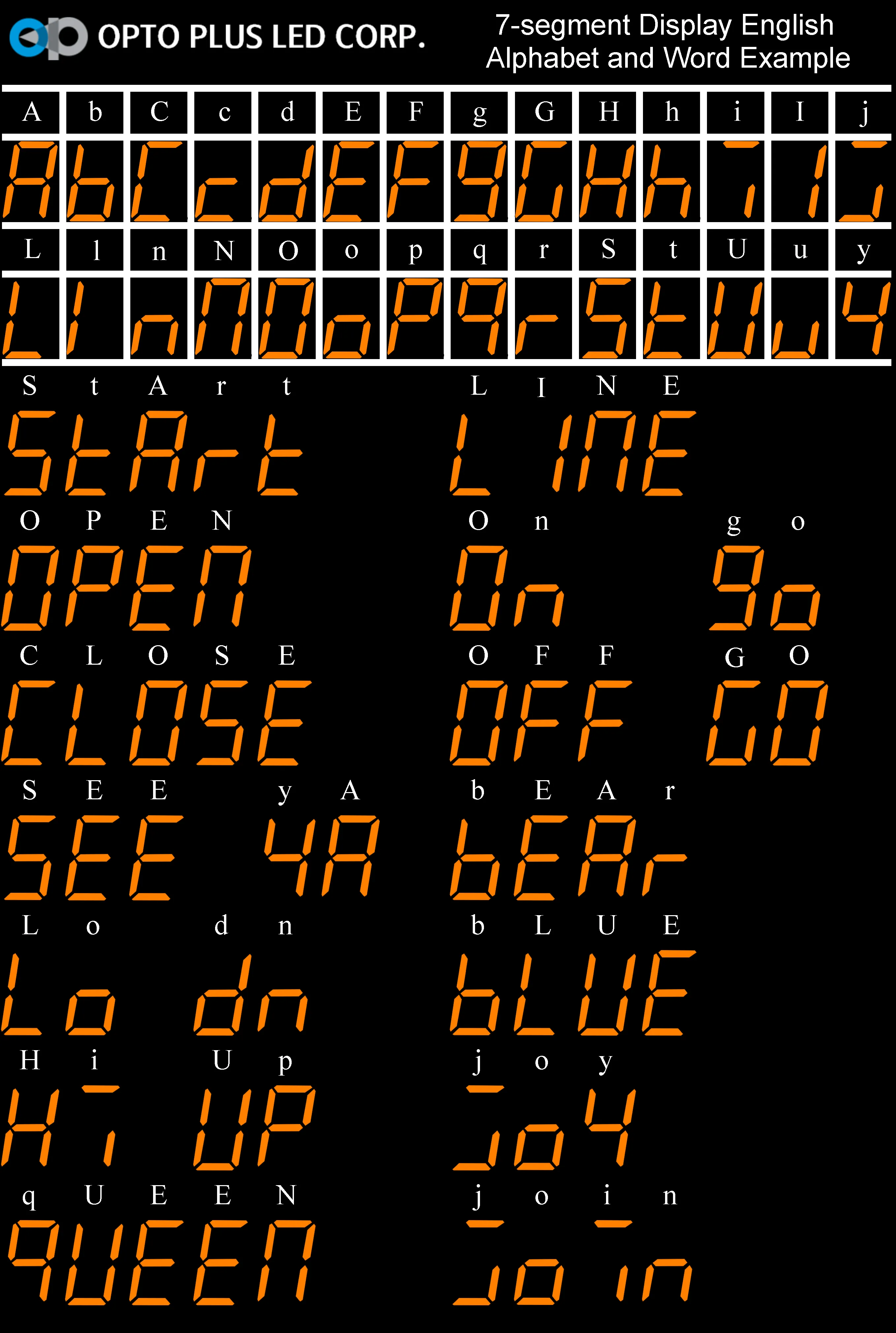
A,b,C,c,d,E,F,g,G,H,h,i,I,j,L,l,n,N,O,o,P,q,r,S,t,U,u,y
The final PCB layout that I ordered from https://jlcpcb.com/ is not great. This is my almost first attempt to really use two sides with a lot of vias. Maybe next time use the lower side for horizontal signal traces and the top side for vertical?
Maybe replace 2.5V ref to MCU with feeding the whole MCU from 2.5V ref, it eliminates the extra wire.
Next time make use wider ribbon cable - use more LEDs on the front panel to indicate the current mode and state
Update the firmware to include trickle charge, it's especially noticeable when charging to the 3.8V for storage, once charging power is removed - voltage drops.
| Qty | Value | Footprint | References |
|---|---|---|---|
| 11 | 10k | Resistor_SMD:R_0805_2012Metric | R2, R6, R7, R8, R10, R11, R20, R21, R22, R24, R25 |
| 4 | 1k | Resistor_SMD:R_0805_2012Metric | R5, R9, R15, R18 |
| 4 | MountingHole | MountingHole:MountingHole_3.2mm_M3 | H1, H2, H3, H4 |
| 4 | MountingHole | MountingHole:MountingHole_2.2mm_M2 | H5, H6, H7, H8 |
| 3 | AO3406 | Package_TO_SOT_SMD:SOT-23 | U5, U9, U10 |
| 2 | 10u | Capacitor_SMD:C_1206_3216Metric | C4, C6 |
| 2 | 1A | !my-lib:PTC_1A_radial | TH1, TH2 |
| 2 | 1N4148 | Diode_SMD:D_MiniMELF | D2, D6 |
| 2 | 2.2k | Resistor_SMD:R_0805_2012Metric | R3, R4 |
| 2 | 470 | Resistor_SMD:R_0805_2012Metric | R13, R16 |
| 2 | 500 | Potentiometer_THT:Potentiometer_Runtron_RM-065_Vertical | RV1, RV2 |
| 2 | BAT54S | Package_TO_SOT_SMD:SOT-23 | D7, D9 |
| 1 | 0.2-0.5R | Resistor_THT:R_Axial_DIN0614_L14.3mm_D5.7mm_P15.24mm_Horizontal | R1 |
| 1 | 100n | Capacitor_SMD:C_1206_3216Metric | C2 |
| 1 | 100p | Capacitor_SMD:C_1206_3216Metric | C8 |
| 1 | 10n | Capacitor_SMD:C_1206_3216Metric | C1 |
| 1 | 10u | Capacitor_THT:CP_Radial_D5.0mm_P2.50mm | C9 |
| 1 | 150R | Resistor_SMD:R_0805_2012Metric | R26 |
| 1 | 1A | LED_THT:LED_D5.0mm | D4 |
| 1 | 1A MODE | Button_Switch_THT:SW_PUSH_6mm | SW2 |
| 1 | 1M | Resistor_SMD:R_0805_2012Metric | R27 |
| 1 | 1N4004 | Diode_THT:D_DO-41_SOD81_P10.16mm_Horizontal | D1 |
| 1 | 1N4732A 4.7V | Diode_SMD:D_MiniMELF | D5 |
| 1 | 1R | Resistor_THT:R_Axial_DIN0614_L14.3mm_D5.7mm_P25.40mm_Horizontal | R12 |
| 1 | 1u | Capacitor_SMD:C_1206_3216Metric | C5 |
| 1 | 2N3904 | Package_TO_SOT_SMD:SOT-23 | Q1 |
| 1 | 2N3906 | Package_TO_SOT_SMD:SOT-23 | Q2 |
| 1 | 2SD2390 | Package_TO_SOT_THT:TO-3P-3_Vertical | Q3 |
| 1 | 2k | Resistor_SMD:R_0805_2012Metric | R14 |
| 1 | 3k | Resistor_SMD:R_0805_2012Metric | R19 |
| 1 | 680 | Resistor_SMD:R_0805_2012Metric | R17 |
| 1 | Arduino_pro_mini | !my-lib:ARDUINO_PRO_MINI_NO_PRG_HEADER | U7 |
| 1 | Buzzer | Buzzer_Beeper:Buzzer_12x9.5RM7.6 | BZ1 |
| 1 | CHARGE | LED_THT:LED_D5.0mm | D3 |
| 1 | CHARGE/DISCHARGE | Button_Switch_THT:SW_PUSH_6mm | SW1 |
| 1 | Charger | Connector_JST:JST_VH_B2P-VH-B_1x02_P3.96mm_Vertical | Battery1 |
| 1 | Conn_DisplayBoard | Connector_IDC:IDC-Header_2x04_P2.54mm_Vertical_SMD | J4 |
| 1 | Conn_MainBoard | Connector_IDC:IDC-Header_2x04_P2.54mm_Vertical | J3 |
| 1 | ISet | Connector_Wire:SolderWire-0.5sqmm_1x01_D0.9mm_OD2.1mm | TP1 |
| 1 | LM2596_StepDown_Module | !my-lib:LM2596_StepDown_pot | U1 |
| 1 | LM358 | Package_SO:SO-8_3.9x4.9mm_P1.27mm | U2 |
| 1 | LOGO | LOGO | G*** |
| 1 | PWR | Connector_JST:JST_XH_B2B-XH-A_1x02_P2.50mm_Vertical | J5 |
| 1 | Pin20 | Connector_Wire:SolderWire-0.5sqmm_1x01_D0.9mm_OD2.1mm | AREF1 |
| 1 | R100 | Resistor_SMD:R_2512_6332Metric | R23 |
| 1 | TL431LP | Package_TO_SOT_THT:TO-92_Wide | U6 |
| 1 | TM1637Display | !my-lib:7segments-medium | U3 |
| 1 | TP4056 | Package_SO:SO-8_3.9x4.9mm_P1.27mm | U8 |
| 1 | X0402MF | Package_TO_SOT_THT:TO-220-3_Vertical | Q6 |


Capibator/hardware
deals with research material on hardware, schematic, pcb design and bom etc.


aaronsilinskas/aura-prototype
A monorepo to prototype Aura Game Engine core features.


It measures 100 × 99.9 mm and has 2 copper layers, 1.6 mm thick.
77 parts, built around the LM358, AO3406, TP4056 and BAT54S. The full list of its parts is on this page, with links to each part's symbol and footprint where PCBKit's library has them.
From the ikatkov/battery-capacity-meter repository on GitHub, at the commit this page was made from: the board is kicad/battery-capacity-meter-2024.kicad_pcb and its schematic kicad/battery-capacity-meter-2024.kicad_sch. PCBKit opens the board in the browser, with nothing to install.
Its repository states no licence, so its author keeps all rights: ask ikatkov before reusing the design.