
4 layers234 × 84 mm
Main panel
google/mozc-devices
Circuit diagrams and firmware source code for Gboard DIY keyboards
234 parts3kApache-2.0

 ssaunter/SwitchTester
A 5-key switch PCB and housing to test the feel of different Cherry MX switches. Addressable LEDs have two modes: always on (colored), and fade when pressed.
SwitchTester is an open-source printed circuit board by ssaunter, from the ssaunter/SwitchTester repository on GitHub. It is a 2-layer board of 122.5 × 26.3 mm with 20 parts on 21 nets, routed with 118 tracks and 1 via.
It is built around the SK6812MINI-E. Its parts include 6 switches, 5 capacitors, 5 diodes, 1 resistor and 1 IC.
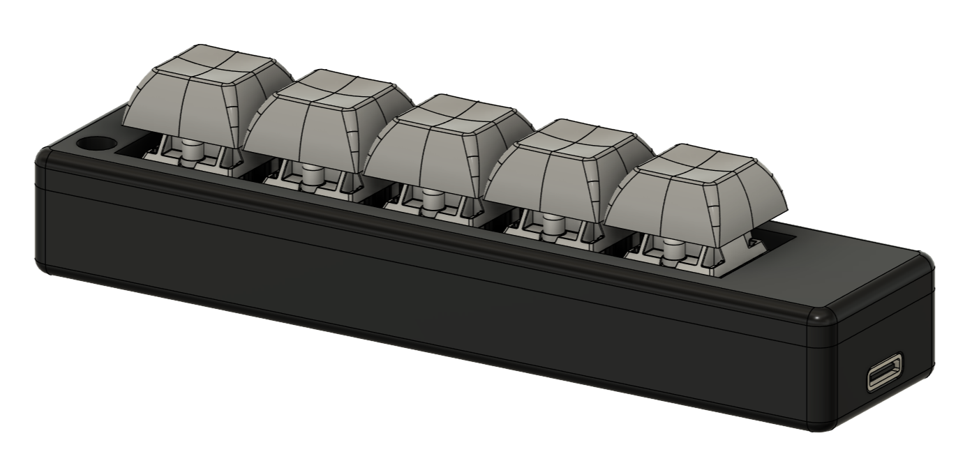
SwitchTester is a 5-key switch PCB and housing to test the feel of different Cherry MX switches. Addressable LEDs have two modes: always on (colored), and fade when pressed.
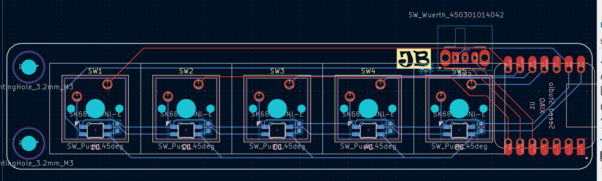
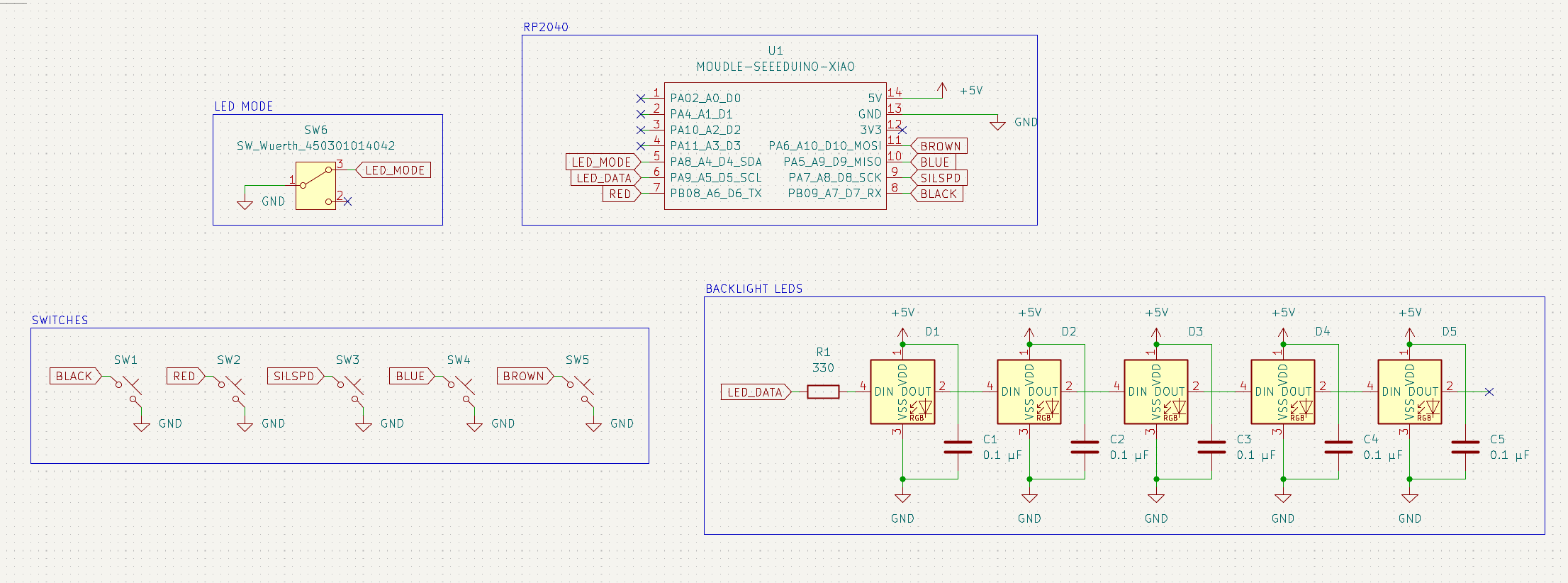
The PCB follows a similar architecture to the Hackpad, and upgrades with decoupling capacitors and a switch to control LED modes. The code is set up to adjust the LED modes depending on the slide switch mode.
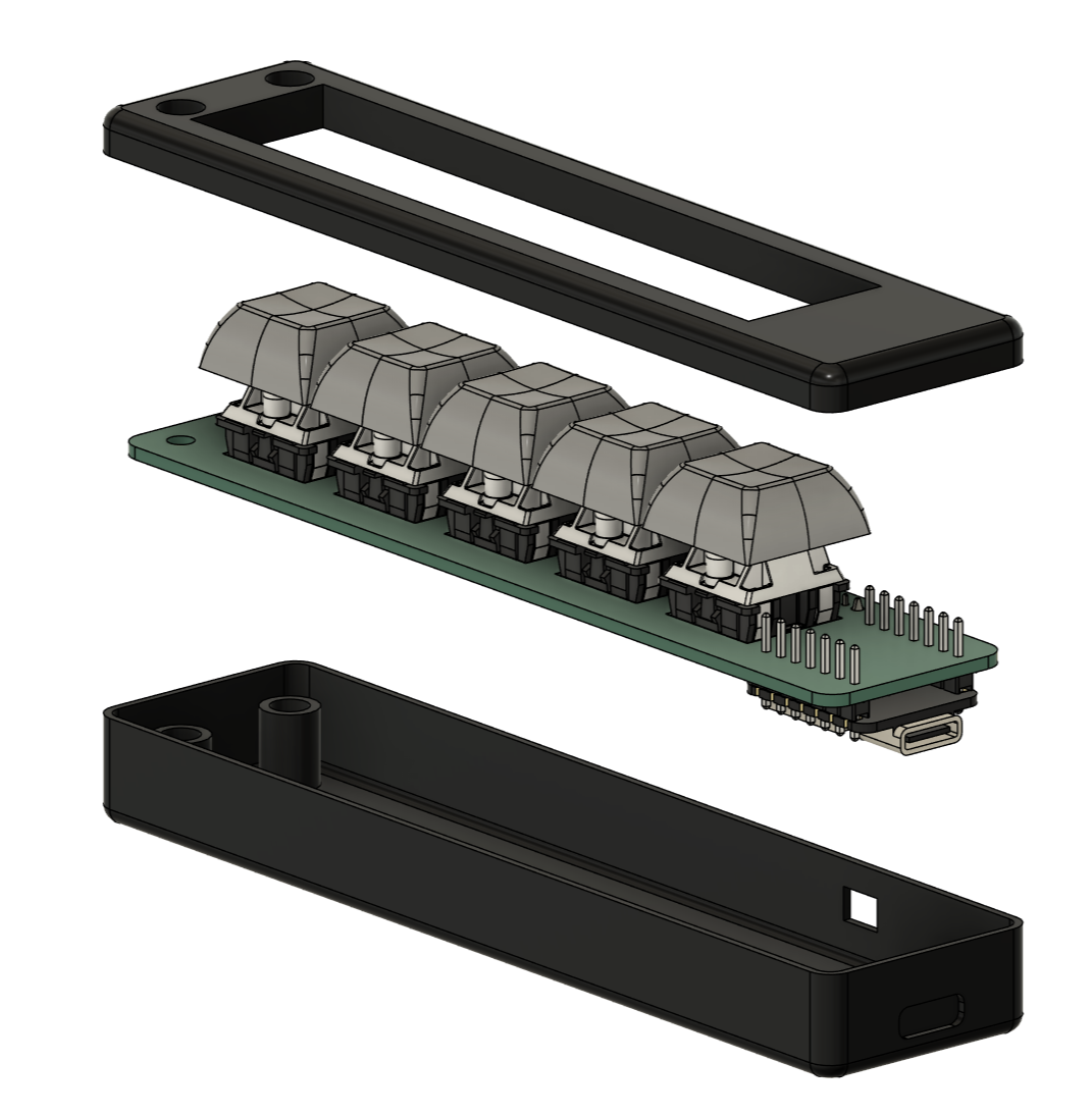
The lower and upper case sections are to be 3D printed. The device is assembled using 2x M3x5x5 heatset inserts and 2x M3x10 bolts. The PCB is aligned in the lower case, and the top case encloses it before being bolted down through the standoffs. It should be stable enough, but the USB-C recepticle also nicely rests into the opposite side for added stability. If I find that it is unstable even then, I can add standoffs without holes thoughout the lower case.
The code was created in the Arduino IDE, and uses the FastLED library for the SMD LEDs. The colors are based on guesses, and I will change the code after testing the values.
The first section of the code is simply setup and definitions. It sets the switches as inputs and assigns the pullup resistors, and also initializes the LED index.
The main loop determines the current LED_MODE, checks for keyswitch presses, and outputs to the LED based on the mode and user interaction. FastLED.show() is used to queue the LED instructions and send data through the LED_DATA line.
| Part | Quantity | Price Per | Link |
|---|---|---|---|
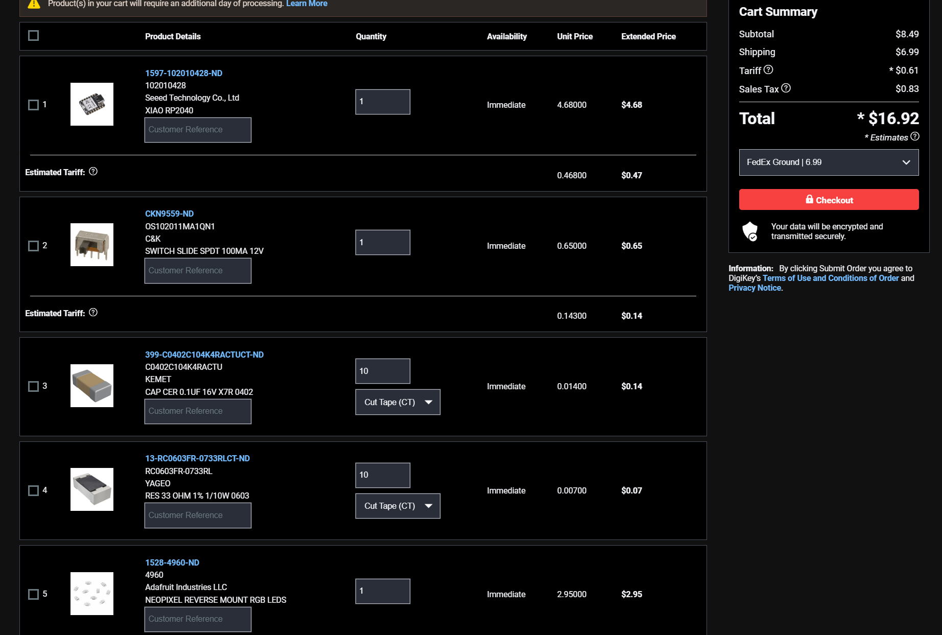
| Seeduino Xiao | 1 | $4.68 | DigiKey |
| Slide Switch | 1 | $0.65 | DigiKey |
| 0.1uF C 0603 | 5 | $0.08 | DigiKey |
| 330ohm R 0603 | 1 | $0.10 | DigiKey |
| Neopixel LED 10pcs | 1 | $2.95 | DigiKey |
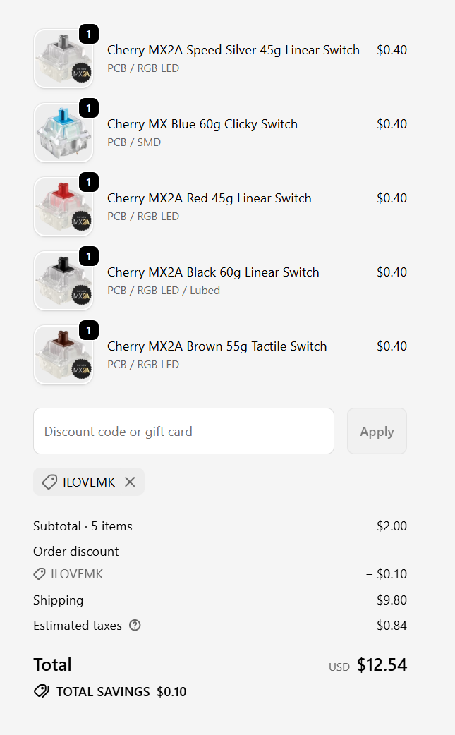
| Cherry MX Blue 60g | 1 | $0.38 | MechanicalKeyboards |
| Cherry MX2A Red | 1 | $0.38 | MechanicalKeyboards |
| Cherry MX2A Black | 1 | $0.38 | MechanicalKeyboards |
| Cherry MX2A Brown | 1 | $0.38 | MechanicalKeyboards |
| Cherry MX Blue 60g | 1 | $0.38 | MechanicalKeyboards |
| DSA Keycaps | 5 | (have) | |
| 1x7 Male Headers | 2 | (have) | |
| M3x5x5 Heatset Inserts | 2 | (have) | |
| M3x10 Bolt | 2 | (have) |
| Service | Price |
|---|---|
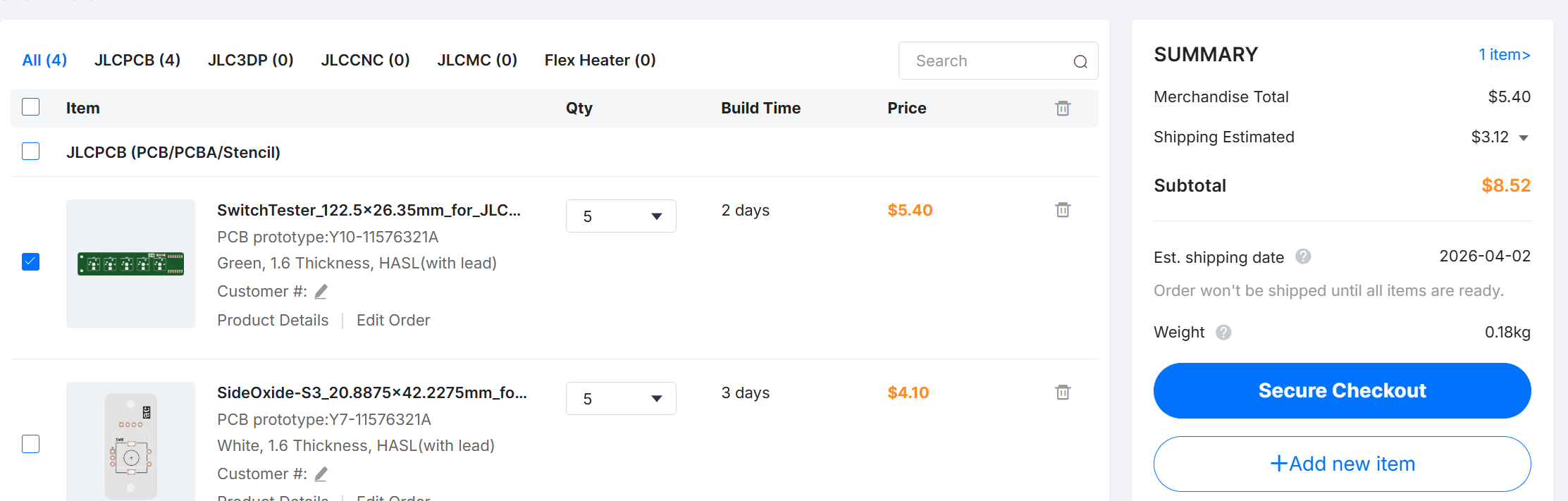
| JLCPCB Order | $8.52 |
| DigiKey Order | $16.92 |
| MechanicalKeyboards Order | $12.54 |
| GRAND TOTAL: | $37.98 |
| Qty | Value | Footprint | References |
|---|---|---|---|
| 5 | 0.1 μF | Capacitor_SMD:C_0603_1608Metric | C1, C2, C3, C4, C5 |
| 5 | SK6812MINI-E | MacroFootprints:SK6812MINI-E_fixed | D1, D2, D3, D4, D5 |
| 5 | SW_Push_45deg | Button_Switch_Keyboard:SW_Cherry_MX_1.00u_PCB | SW1, SW2, SW3, SW4, SW5 |
| 1 | 330 | Resistor_SMD:R_0603_1608Metric | R1 |
| 1 | MOUDLE-SEEEDUINO-XIAO | MacroFootprints:XIAO-Generic-Hybrid-14P-2.54-21X17.8MM | U1 |
| 1 | SW_Wuerth_450301014042 | Button_Switch_THT:SW_Slide_SPDT_Angled_CK_OS102011MA1Q | SW6 |
The 18 most common of 20 parts.
It measures 122.5 × 26.3 mm and has 2 copper layers, 1.6 mm thick.
20 parts, built around the SK6812MINI-E. The full list of its parts is on this page, with links to each part's symbol and footprint where PCBKit's library has them.
From the ssaunter/SwitchTester repository on GitHub, at the commit this page was made from: the board is pcb/SwitchTester.kicad_pcb and its schematic pcb/SwitchTester.kicad_sch. PCBKit opens the board in the browser, with nothing to install.
Its repository states no licence, so its author keeps all rights: ask ssaunter before reusing the design.
google/mozc-devices
Circuit diagrams and firmware source code for Gboard DIY keyboards

Bastardkb/Dilemma
The Dilemma is a vertical stagger low-profile keyboard with mods.

Pwnsat/FlatSat
Flatsat v1.0 is a hardware based platform for aerospace cybersecurity research

adamws/kicad-kbplacer
KiCad plugin for automatic keyboard's key placement and routing

imchipwood/dumbpad
Simple 4x4 numpad with rotary encoder. Powered by QMK via ATmega32u4 Pro Micro

makerforgetech/modular-biped
An open source framework for creating a bipedal modular companion robot.

