2 layers64.6 × 67.3 mm
VMFB MC
src1138/VMFB-MC
Simplified version of the VMFB PCB designed to rely on a microcontroller
47 parts1GPL-3.0
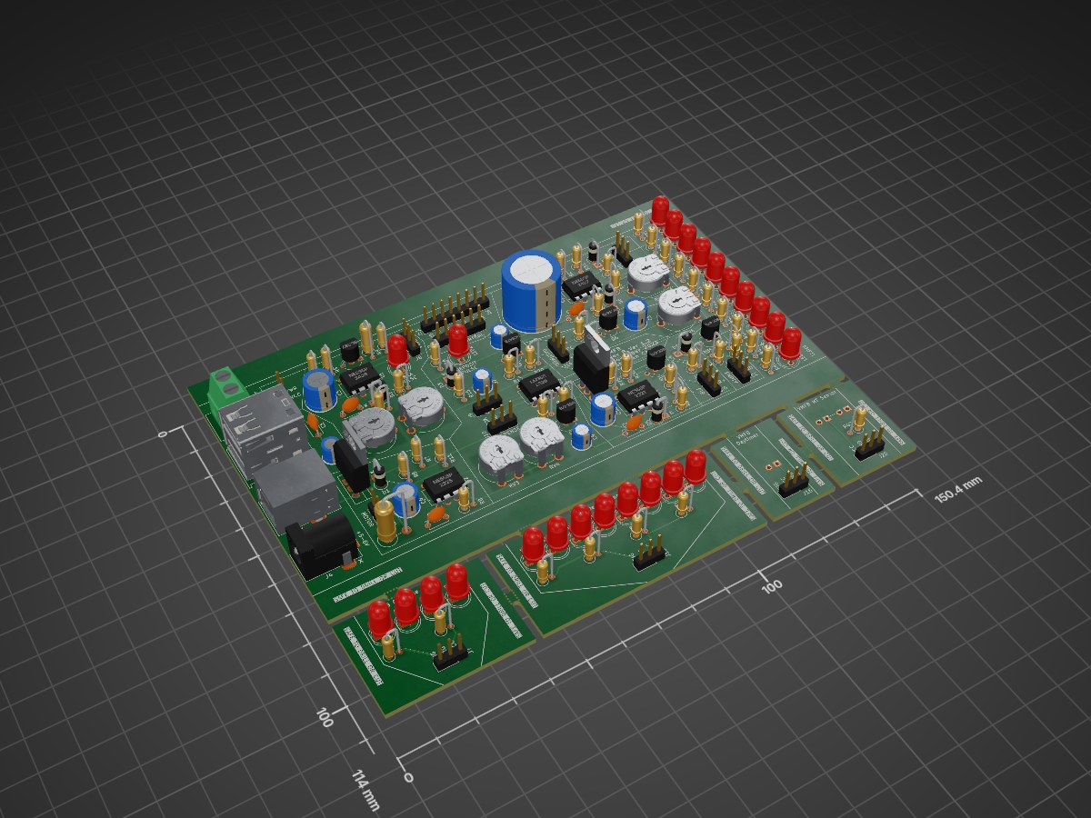
 src1138/VMFB2
Simple, inexpensive bird feeder that dispenses peanuts in exchange for dropping stuff in a hole. A vending machine for clever birds.
VMFB is an open-source printed circuit board by src1138, from the src1138/VMFB repository on GitHub. It is a 2-layer board of 150.4 × 114 mm with 138 parts on 93 nets, routed with 805 tracks and 2 vias.
It is built around the LM358, NE555P and SFH 313 FA-2/3, with the BC547B, TIP120 and BC337 among its other parts. Its parts include 48 resistors, 20 diodes, 19 connectors, 14 capacitors and 8 transistors.


A vending machine for birds that rewards them with food when they drop something in a hole. Electronics and enclosure materials cost <100 USD/EUR. I've designed a PCB and PVC pipe enclosure and dispenser (described below). The circuit is not complex, but I think a custom PCB makes it easier for people who are not electronics hobbyists to build this. I've made a few different enclosures ouot of scrap for this, but will share the PVC pipe enclosure details since it's sturdy, waterproof, and the materials can all be found at the hardware store.
There were two main inspirations for me to start and document this project
The circuit is all analog, using four NE555 timers and one LM358 dual op amp. The sensors are all made using IR phototransistors and IR LEDs. The PCB has headers broken out so you can monitor and control it with a microcontroller or SBC. It runs on 5-6VDC and uses ~10mA in standby (~20mA if timer and powerbank keep-alive are enabled), ~250mA when IR LEDs are on and ~400mA when the dispenser motor is running. A 10,000 mAh USB powerbank should last about a week.
Kicad Files (Github): https://github.com/src1138/VMFB
Gerbers and PCB (PCBWay): https://www.pcbway.com/project/shareproject/Vending_Machine_for_Birds_eda585b3.html
Front
Back
The PCB has footprints for USB type A, USB type B, barrel jack and screw terminal power input. You only need to populate the ones you will use.
In Rev.B Ver.1.0 you need to add a 10K resistor on the EMPTY sensor from the SIGNAL header pin to ground.
The Timer and Powerbank Keep-Alive are not essential and you don't have to populate the parts for them if you don't need/want to use them.
This project uses commodity components, and you can confidently use alternatives with similar specs. There are a few points to keep in mind.
When timed dispense is triggered, it sends a signal to turn on the sensor IR LEDs and triggers the motor controller to start the vibration dispenser. When something is dispensed, the motor stops.
I was using a Rasperry Pi Zero W with a wide-angle camera module with my vending machine, but I wanted something that drew less power (and was cheaper and more available). I found that the ESP32-CAM module consumes about 135 MA when streaming video, can be put to sleep (consuming just a few mA) and has 4 GPIO pins available when using the SD-card slot - it can stream/record video and log events from the vending machine, making it all available over wifi or bluetooth.
I'm still in the process of modifying the ESP32-CAM example program to monitor/log events and stream video, record video files to SD, and sleep until the PIR is triggered. I will put this code on Github when it's ready.
Dispenser: two-layer vibration platform with offset holes made from 3mm PVC sheet and 15mm M3 brass standoffs. I used a small 24x12mm 2VDC motor attached to the dispenser with brass standoffs and 3mm PVC sheet.
Enclosure: made from 110mm and 50mm PVC pipe and joints, 32mm PVC joints, a 35mm plastic tray and a 1.5l PET bottle.
Mounting: can be mounted on the ground, horizontal or vertical railing, wooden fence, wall, pole The dispenser typically dispenses a peanut or two within 3 seconds. Since it is a vibration dispenser, the enclosure should be level and mounted securely to insure relaible dispensing.
The dispenser drops peanuts into a funnel made from the top of the PET bottle. There is about 12cm between the two, making it difficult for rodents small enough to get into the machine to get to the food. PVC is tough enough to keep larger rodents from gnawing or breaking thier way in.
I used peanuts in the shell to attract birds to the area and shelled peanuts in the vending machine. If you live in an area with lots of pigeons, using peanuts in the shell will not attract them as much since they can't eat them (can't get he shell off) and you have a better chance of attracting corvids. Shelled peanuts are easier to dispense reliably - peanuts in the shell are less dense, more irregular in shape, and jam easily. Dry cat and dog food also works.
Along with learning and having some fun, the goal is to get a birds to bring something, drop it in a hole, and get a reward. Birds need some conditioning for this, so there are a few phases to progress though to help them figure this out.
0 - Put food in the area you plan to mount the vending machine to start attracting birds (1-2 weeks) 1 - Food Provided, Timed Dispense, Deposit Provided (2-3 weeks) 2 - No Food Provided, Timed Dispense, Deposit Provided (3-4 months) 3 - No Food Provided, No Timed Dispense, Deposit Provided (6-8 months) 4 - No Food Provided, No Timed Dispense, No Deposit Provided
Time estimates are based on my own experience over the past year or so, but Phase 3 duration is a guess. As of July 2023 I have not yet seen a bird deposit an item I didn't provide. Unfortunately I had to take my machine down in May due to some new HOA regulations prohibiting feeding the birds in my neighborhood. I plan to redeploy it when I find another suitable location.
The PVC enclosure contains the battery, electronics and sensors, dispenser, peanuts, and deposited items. The platform is a 35cm plastic tray for a plant pot, attached to the deposit chute with 4 90-degree brackets, four M4 bolts and two hose clamps.
I used bits of electrical or duct tape to make the PVC pipes and joints fit securely tight. This way it is easy to disassemble/modify/repair. It's a good idea to wrap upward-facing joints to prevent water ingress during heavy rains.
You can load peanuts (or whatever) by unscrewing the top cap and pouring them in. I made two baffles from 3mm PVC sheet to reduce the pressure on the vibration dispenser.
You can unload the deposited items by unscrewing one of the caps on the lower half of the vending machine.
| Qty | Value | Footprint | References |
|---|---|---|---|
| 29 | 10K | Resistor_THT:R_Axial_DIN0207_L6.3mm_D2.5mm_P2.54mm_Vertical | R3, R11, R13, R14, R17, R18, R20, R21, R23, R25, R26, R27, R30, R31, R33, R35 +13 |
| 12 | Signal LED | LED_THT:LED_D5.0mm | LED1, LED2, LED3, LED4, LED5, LED6, LED7, LED8, LED9, LED10, LED11, LED12 |
| 11 | Conn_01x03_Pin | Connector_PinHeader_2.54mm:PinHeader_1x03_P2.54mm_Vertical | J7, J8, J9, J10, J13, J14, J15, J16, J17, J18, J20 |
| 8 | SFH313FA-2/3 | LED_THT:LED_D5.0mm | QP1, QP2, QP3, QP4, QP5, QP6, QP7, QP8 |
| 7 | 100R | Resistor_THT:R_Axial_DIN0207_L6.3mm_D2.5mm_P2.54mm_Vertical | R1, R2, R12, R16, R19, R22, R47 |
| 7 | 1N4007 | Diode_THT:D_DO-41_SOD81_P2.54mm_Vertical_KathodeUp | D1, D2, D3, D4, D5, D6, D7 |
| 7 | IR LED | LED_THT:LED_D5.0mm | IR1, IR2, IR3, IR4, IR5, IR6, IR7 |
| 5 | 10nF | Capacitor_THT:C_Disc_D5.0mm_W2.5mm_P5.00mm | C1, C5, C6, C12, C13 |
| 5 | BC547B | Package_TO_SOT_THT:TO-92_Inline_Wide | Q3, Q4, Q6, Q7, Q8 |
| 4 | 100K | Potentiometer_THT:Potentiometer_Piher_PT-10-V10_Vertical | RV1, RV3, RV4, RV6 |
| 4 | NE555P | Package_DIP:DIP-8_W7.62mm | U1, U2, U4, U5 |
| 3 | 100uF | Capacitor_THT:CP_Radial_D6.3mm_P2.50mm | C4, C10, C14 |
| 2 | 100K | Resistor_THT:R_Axial_DIN0207_L6.3mm_D2.5mm_P2.54mm_Vertical | R8, R15 |
| 2 | 10uF | Capacitor_THT:CP_Radial_D5.0mm_P2.00mm | C2, C7 |
| 2 | 1uF | Capacitor_THT:CP_Radial_D5.0mm_P2.00mm | C8, C9 |
| 2 | 220K | Resistor_THT:R_Axial_DIN0207_L6.3mm_D2.5mm_P2.54mm_Vertical | R28, R29 |
| 2 | 470R | Resistor_THT:R_Axial_DIN0207_L6.3mm_D2.5mm_P2.54mm_Vertical | R24, R34 |
| 2 | Conn_01x02_Pin | Connector_PinHeader_2.54mm:PinHeader_1x02_P2.54mm_Vertical | J5, J6 |
| 2 | LOGO | LOGO | DIRTY BIRD, Small Dirty Bird |
| 2 | TIP120 | Package_TO_SOT_THT:TO-220-3_Vertical | Q1, Q5 |
| 1 | 10K | Potentiometer_THT:Potentiometer_Piher_PT-10-V10_Vertical | RV2 |
| 1 | 10R | Resistor_THT:R_Axial_DIN0414_L11.9mm_D4.5mm_P5.08mm_Vertical | R48 |
| 1 | 1K | Resistor_THT:R_Axial_DIN0207_L6.3mm_D2.5mm_P2.54mm_Vertical | R32 |
| 1 | 2.2K | Resistor_THT:R_Axial_DIN0207_L6.3mm_D2.5mm_P2.54mm_Vertical | R4 |
| 1 | 220uF | Capacitor_THT:CP_Radial_D8.0mm_P3.50mm | C3 |
| 1 | 2M | Potentiometer_THT:Potentiometer_Piher_PT-10-V10_Vertical | RV5 |
| 1 | 4.7K | Resistor_THT:R_Axial_DIN0207_L6.3mm_D2.5mm_P2.54mm_Vertical | R10 |
| 1 | 4700uF | Capacitor_THT:CP_Radial_D16.0mm_P7.50mm | C11 |
| 1 | 47K | Resistor_THT:R_Axial_DIN0207_L6.3mm_D2.5mm_P2.54mm_Vertical | R6 |
| 1 | 47R | Resistor_THT:R_Axial_DIN0309_L9.0mm_D3.2mm_P2.54mm_Vertical | R9 |
| 1 | 5.1V | Diode_THT:D_DO-41_SOD81_P2.54mm_Vertical_KathodeUp | D8 |
| 1 | BC337 | Package_TO_SOT_THT:TO-92_Inline_Wide | Q2 |
| 1 | Barrel_Jack_Switch | Connector_BarrelJack:BarrelJack_Horizontal | J4 |
| 1 | Center Pos | LOGO | Polarity |
| 1 | Conn_01x06_Pin | Connector_PinHeader_2.54mm:PinHeader_1x06_P2.54mm_Vertical | J12 |
| 1 | Conn_01x08_Pin | Connector_PinHeader_2.54mm:PinHeader_1x08_P2.54mm_Vertical | J11 |
| 1 | LM358 | Package_DIP:DIP-8_W7.62mm | U3 |
| 1 | Screw_Terminal_01x02 | TerminalBlock:TerminalBlock_Altech_AK300-2_P5.00mm | J1 |
| 1 | USB_A_Stacked | Connector_USB:USB_A_Wuerth_61400826021_Horizontal_Stacked | J2 |
| 1 | USB_B | Connector_USB:USB_B_Lumberg_2411_02_Horizontal | J3 |
It measures 150.4 × 114 mm and has 2 copper layers, 1.6 mm thick.
138 parts, built around the LM358, NE555P, SFH 313 FA-2/3 and BC547B. The full list of its parts is on this page, with links to each part's symbol and footprint where PCBKit's library has them.
From the src1138/VMFB repository on GitHub, at the commit this page was made from: the board is VMFB.kicad_pcb and its schematic VMFB.kicad_sch. PCBKit opens the board in the browser, with nothing to install.
Its repository states no licence, so its author keeps all rights: ask src1138 before reusing the design.
src1138/VMFB-MC
Simplified version of the VMFB PCB designed to rely on a microcontroller

polish-space-agency/key-to-space
PL: Cała zawartość tego repozytorium, w tym pliki projektowe programu KiCad (schematy i projekty płytek PCB) oraz dokumentacja techniczna, udostępniana jest na licencji: Creative Commons Uznanie autorstwa - Użycie…

RobertPHeller/CommandStationsAndBoosters
Command Stations and Boosters


