

2 layers87.7 × 254.8 mm
 SpokeSpice/Hardware1
Schematics and layouts
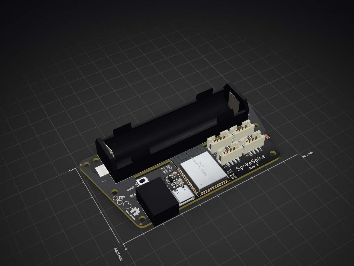
Controller is an open-source printed circuit board by SpokeSpice, from the SpokeSpice/Hardware repository on GitHub, published under the CERN-OHL-S-2.0 licence. It is a 4-layer board of 98.5 × 48.5 mm with 40 parts on 51 nets, routed with 223 tracks and 59 vias.
It is built around the ESP32-S3-WROOM-1-N8. Its parts include 8 resistors, 6 connectors, 3 capacitors, 3 diodes and 2 ICs. It belongs with the ESP32 boards of this library.
The project is divided into two parts, the controller and the arms. Typically a system would have 4 arms, each running at an angle of 90 degrees to the next.
This repository contains the KiCad project files for the controller and the arm PCBs.
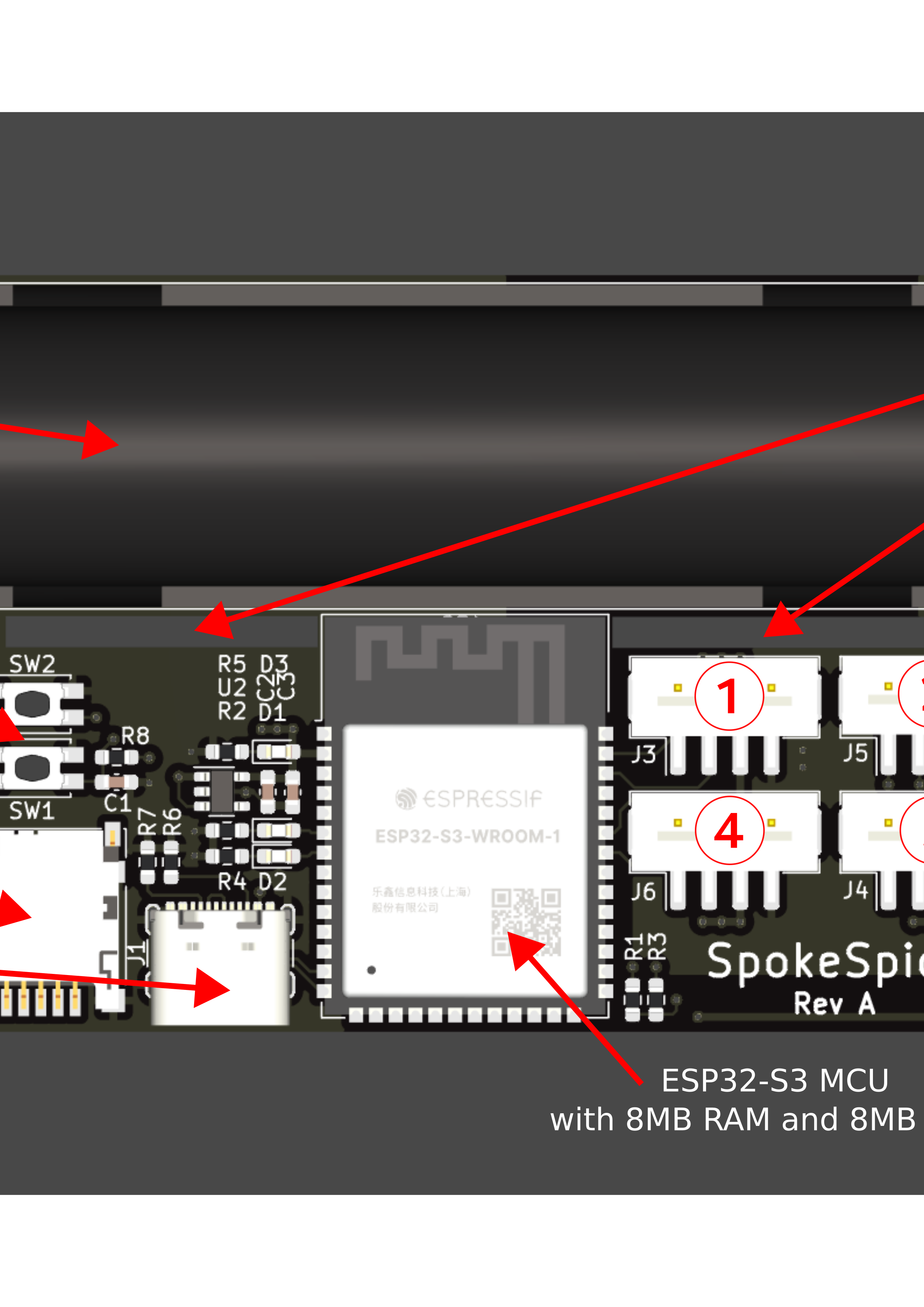
The controller board is based on the ESP32 microcontroller and features a USB-C connector for programming. It features a battery holder for an 18650 Li-Ion cell, a 3.3V LDO regulator, an SD card slot and 4 connectors for the arms.
Several mounting holes in the PCB allow it to be mounted in a variety of different spoke configurations.
For the sake of simplicity, the controller board does not feature a battery charging circuit. The battery must be charged externally.
There is also no voltage regulation for the LEDs. The LEDs are powered directly from the battery, which is a 3.7V cell. Consequently, there is also no reverse polarity protection to avoid the voltage drop and hence the energy loss. The battery must hence be inserted with the correct polarity.
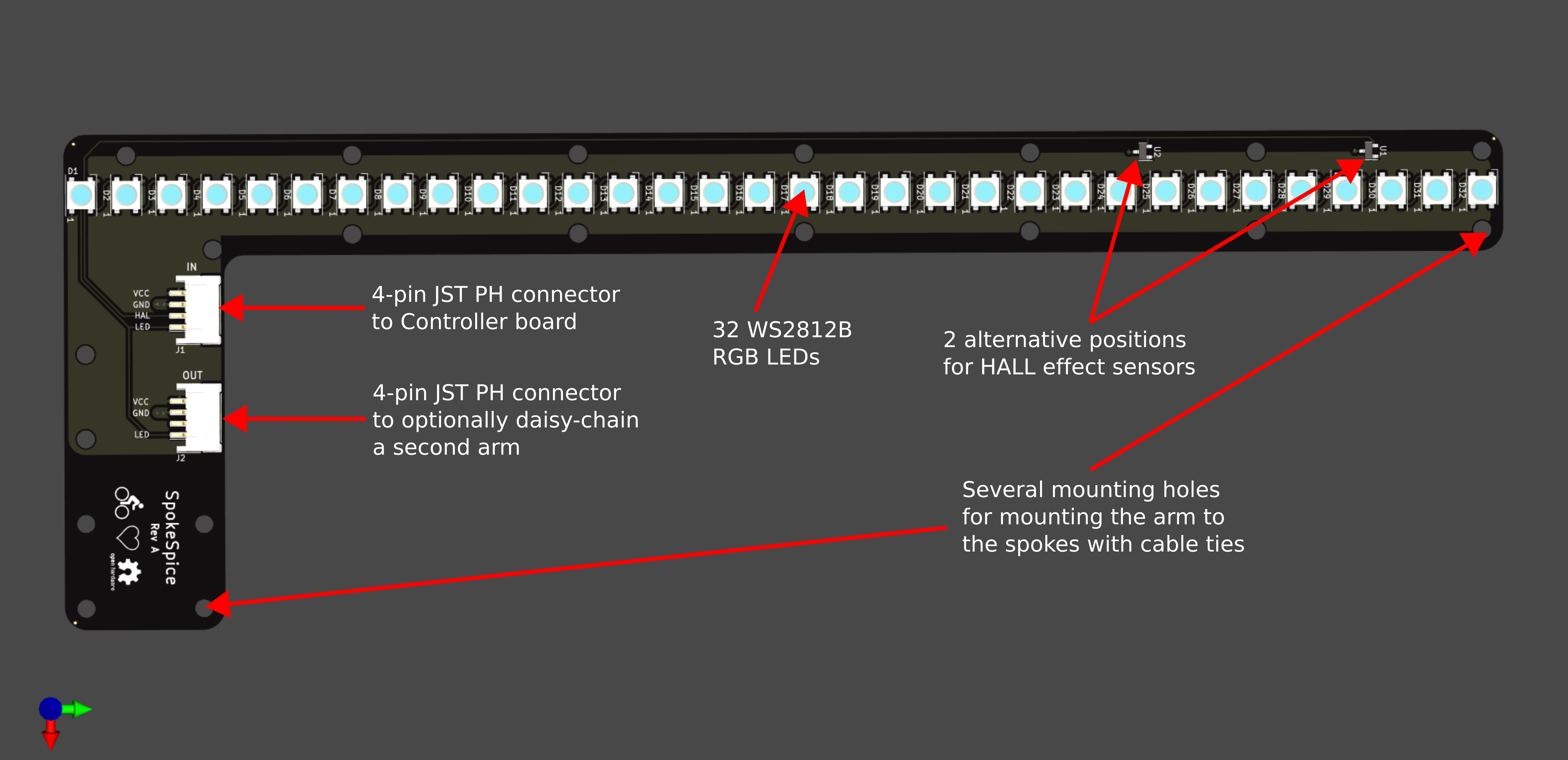
Arms are made to be attached to the spokes of a 28-inch bicycle wheel.
Several mounting holes in the PCB allow them to be mounted in a variety of different spoke configurations.
Each arm PCB features 32 WS2812B RGB LEDs and is connected to the controller board via a 4-pin cable. A second 4-pin cable can be used to daisy-chain a second arm on the other side of the wheel, which will then display the same content.
A hall effect sensor is used to detect the speed of the wheel and to synchronize the display with the rotation. There are two positions for this sensor.
As the controller and the arms are mounted to the spokes with cable ties, it's recommended to install everything on a spare wheel that you mount and dismount from the bicycle as needed.
Several additional components are needed to build the project:
If you would like to contribute to the project, please open an issue or a pull request.

This project is licensed under the CERN Open Hardware License v2. You may redistribute and modify this project under the terms of the CERN-OHL-S v2 (https://ohwr.org/cern_ohl_s_v2.txt). This documentation is distributed without any warranty. Without even the implied warranty of merchantability or fitness for a particular purpose.
| Qty | Value | Footprint | References |
|---|---|---|---|
| 8 | MountingHole | MountingHole:MountingHole_3.2mm_M3 | H1, H2, H3, H4, H5, H6, H7, H8 |
| 4 | Conn_01x04 | Connector_JST:JST_PH_B4B-PH-SM4-TB_1x04-1MP_P2.00mm_Vertical | J3, J4, J5, J6 |
| 3 | 10k | Resistor_SMD:R_0603_1608Metric_Pad0.98x0.95mm_HandSolder | R1, R3, R8 |
| 3 | 1k | Resistor_SMD:R_0603_1608Metric_Pad0.98x0.95mm_HandSolder | R2, R4, R5 |
| 3 | Fiducial | Fiducial:Fiducial_0.5mm_Mask1mm | FID1, FID2, FID3 |
| 3 | LED 10 mA green | LED_SMD:LED_0603_1608Metric_Pad1.05x0.95mm_HandSolder | D1, D2, D3 |
| 2 | 5.1k | Resistor_SMD:R_0603_1608Metric_Pad0.98x0.95mm_HandSolder | R6, R7 |
| 2 | SW_Push | Button_Switch_SMD:SW_SPST_EVQP2 | SW1, SW2 |
| 1 | 0.1uF | Capacitor_SMD:C_0603_1608Metric_Pad1.08x0.95mm_HandSolder | C3 |
| 1 | 10uF | Capacitor_SMD:C_0603_1608Metric_Pad1.08x0.95mm_HandSolder | C2 |
| 1 | 1uF | Capacitor_SMD:C_0603_1608Metric_Pad1.08x0.95mm_HandSolder | C1 |
| 1 | Battery_Cell | Battery:BatteryHolder_Keystone_1042_1x18650 | BT1 |
| 1 | ESP32-S3-WROOM-1 | RF_Module:ESP32-S3-WROOM-1 | U1 |
| 1 | Micro_SD_Card_Det | Connector_Card:microSD_HC_Hirose_DM3D-SF | J2 |
| 1 | NCP163ASN330T1G | Package_TO_SOT_SMD:SOT-23-5 | U2 |
| 1 | SolderJumper_2_Open | Jumper:SolderJumper-2_P1.3mm_Open_Pad1.0x1.5mm | JP1 |
| 1 | USB_C_Receptacle_USB2.0_14P | Connector_USB:USB_C_Receptacle_GCT_USB4105-xx-A_16P_TopMnt_Horizontal | J1 |
The 37 most common of 40 parts.
It measures 98.5 × 48.5 mm and has 4 copper layers, 1.6 mm thick.
40 parts, built around the ESP32-S3-WROOM-1-N8. The full list of its parts is on this page, with links to each part's symbol and footprint where PCBKit's library has them.
From the SpokeSpice/Hardware repository on GitHub, at the commit this page was made from: the board is Controller/A/Controller.kicad_pcb and its schematic Arm/A/Arm.kicad_sch. PCBKit opens the board in the browser, with nothing to install.
Its repository publishes it under the CERN-OHL-S-2.0 licence: you may reuse it on that licence's terms (keep the author's notice, and for a copyleft licence share your changes alike).

joeycastillo/The-Open-Book
For details on how to build, test and use Open Book, I've made documentation available here.

hackclub/OnBoard
💡 Join 1,000 teenagers and make your first PCB with a $100 grant!

bitaxeorg/bitaxeGamma
Bitaxe based on the BM1370 from the S21 Pro


hhuysqt/esp32s3-keyboard
USB/BLE keyboard driver based on ESP32S3-WROOM-1

katbinaris/nanofoc_devkit
Compact All-In-One BLDC Controler featuiring ESP32-S3, TMC6300 and Magalpha sensors. Small 35x35mm footprint.

Hack-a-Day/2025-Communicator_Badge
The 2025 Hackaday Supercon RF Communicator Badge