4 layers55.9 × 30.5 mm

 katbinaris/nanofoc_devkit146
Compact All-In-One BLDC Controler featuiring ESP32-S3, TMC6300 and Magalpha sensors. Small 35x35mm footprint.
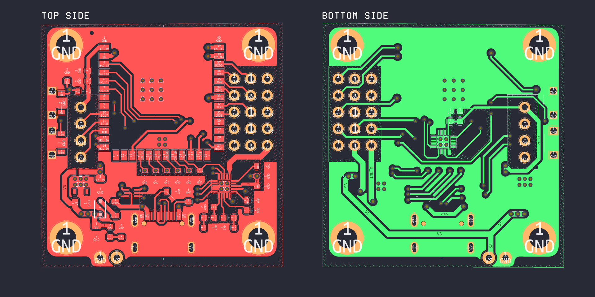
BinNanoFOC is an open-source printed circuit board by katbinaris, from the katbinaris/nanofoc_devkit repository on GitHub. It is a 2-layer board of 35.1 × 36.6 mm with 76 parts on 72 nets, routed with 389 tracks and 68 vias.
It is built around the ESP32-S3-WROOM-1-N8, MAQ430GQE-AEC1-P and TMC6300-LA, with the ST1L05CPU33R among its other parts. Its parts include 14 resistors, 12 capacitors, 4 ICs, 3 diodes and 2 switches. It belongs with the robots and motor control and sensors and measurement boards and the ESP32 boards of this library.


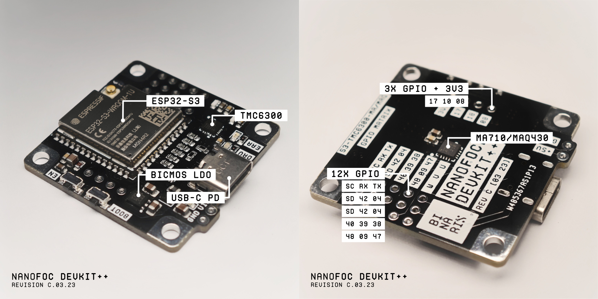
Starting your first Field Oriented Control (FOC) project might be daunting, especially if you're new to the field.
As makers, we frequently want to jump right into the action and begin writing the firmware without the hassle/need of selecting the right Microcontroller, Magnetic Sensor, and Motor Driver, then configuring and calibrating it with an abundance of cables that renders your projects too bulky to use in your creations.
The NanoFOC is little enough to attach on the back of most small BLDC gimbal motors (Even easier with Universal BLDC Motor Adapter Kit), making it an excellent choice for compact projects requiring maximum efficiency and precision.
Purchase Link: https://store.binaris.io/products/nanofoc-devkit
| Pin | Function | On GPIO Matrix? |
|---|---|---|
| GPIO 01 | I2C SCL | YES |
| GPIO 02 | I2C SDA | YES |
| GPIO 04 | SPI CS -MAGNETIC SESNOR | NO |
| GPIO 05 | SPI MOSI -MAGNETIC SESNOR | NO |
| GPIO 06 | SPI SCLK -MAGNETIC SESNOR | NO |
| GPIO 07 | SPI MISO -MAGNETIC SESNOR | NO |
| GPIO 08 | I/O | YES |
| GPIO 09 | I/O | YES |
| GPIO 10 | VL - PhaseB Low | NO |
| GPIO 11 | WL - PhaseC Low | NO |
| GPIO 12 | UL - PhaseA Low | NO |
| GPIO 13 | WH - PhaseC High | NO |
| GPIO 14 | VH - PhaseB High | NO |
| GPIO 17 | I/O | YES |
| GPIO 18 | I/O | YES |
| GPIO 19 | USB D- | NO |
| GPIO 20 | USB D+ | NO |
| GPIO 21 | UH PhaseA High | NO |
| GPIO 38 | I/O | YES |
| GPIO 39 | I/O | YES |
| GPIO 40 | I/O | YES |
| GPIO 41 | I/O | YES |
| GPIO 42 | I/O | YES |
| GPIO 43 | UART0 TX or I/O | YES |
| GPIO 44 | UART0 RX or I/O | YES |
| GPIO 43 | UART0 TX | YES |
| GPIO 44 | UART0 RX | YES |
| GPIO 47 | I/O | YES |
| GPIO 48 | I/O | YES |
Device is designed to run of 5V @ 1.5A Max. There are two ways you can power the board
USB Type C - Power delivery is capped at 5V3A with usage of 5.1K resistors on CC1 and CC2 pads. It is recommended to use USB that is PD2.0 compatible. It is possible to power device off 500mA capable USB port - however this is not recommended.
External VIN - This connection bypass L1 and D4 connecting directly to Driver and LDO VS pin. The recommended input voltage is 5V and maximum allowed is 6V - which is restricted by max VIN of ST1L05C LDO.
Development Kit comes with no Firmware. Since ESP32-S3 comes with USB-OTG/USB-Serial integrated into MCU the assumption is that this would be a preferred method of code upload. If you are connecting your device to computer for the first time it is critical to put device into DFU mode.
In order to do that you need to:
Alternatively you may use UART pins which are available on GPIO Matrix to upload your code the legacy way. In order to do that you need external TTL Converter.
SmartKnob by Scott Bezek -> https://github.com/scottbez1/smartknob#nanofoc-3rd-party
| Qty | Value | Footprint | References |
|---|---|---|---|
| 23 | , , , , , , , , , , , , , , , +7 | ||
| 6 | 100K | Resistor_SMD:R_0603_1608Metric | R1, R2, R3, R4, R5, R6 |
| 5 | 100nF | Capacitor_SMD:C_0603_1608Metric | C1, C2, C4, C8, C12 |
| 2 | 1uF | Capacitor_SMD:C_0603_1608Metric | C7, C13 |
| 2 | 300M | Resistor_SMD:R_0603_1608Metric | R9, R10 |
| 2 | 300R | Resistor_SMD:R_0603_1608Metric | R7, R8 |
| 2 | 4.7uF | Capacitor_SMD:C_0805_2012Metric | C5, C6 |
| 2 | 5.1K | Resistor_SMD:R_0603_1608Metric | R13, R13 |
| 2 | SW_MEC_5E | Button_Switch_SMD:SKTDLDE010 | SW1, SW2 |
| 1 | 100Mhz 40Ohm 1.5A | Inductor_SMD:L_0805_2012Metric | L1 |
| 1 | 10K | Resistor_SMD:R_0603_1608Metric | R15 |
| 1 | 10uF | Capacitor_SMD:C_0603_1608Metric | C3 |
| 1 | 22uF | Capacitor_SMD:C_0603_1608Metric | C11 |
| 1 | 22uF | Capacitor_SMD:C_0805_2012Metric | C9 |
| 1 | 350R | Resistor_SMD:R_0603_1608Metric | R14 |
| 1 | D | Diode_SMD:D_SOD-323 | D4 |
| 1 | DRIVER | LED_SMD:LED_0603_1608Metric | DRV |
| 1 | ERROR | LED_SMD:LED_0603_1608Metric | DIAG |
| 1 | ESP32-S3-WROOM-1 | Espressif:ESP32-S3-WROOM-1U | U1 |
| 1 | LED | LED_SMD:LED_0603_1608Metric | D5 |
| 1 | MAQ430GQE-AEC1-P | MAQ430:MAQ430GQE-AEC1-P | U3 |
| 1 | NUF2042XV6T1G | Package_TO_SOT_SMD:SOT-563 | D3 |
| 1 | ST1L05CPU33R | ST1L05 LDO:SON95P300X300X100-7N-D | IC1 |
| 1 | TMC6300-LA | TMC6300-LA:TMC6300-LA | U2 |
| 1 | USB_C_Plug | Connector_USB:USB_C_Receptacle_G-Switch_GT-USB-7010ASV | P1 |
The 62 most common of 76 parts.
It measures 35.1 × 36.6 mm and has 2 copper layers, 1.6 mm thick.
76 parts, built around the ESP32-S3-WROOM-1-N8, MAQ430GQE-AEC1-P, TMC6300-LA and ST1L05CPU33R. The full list of its parts is on this page, with links to each part's symbol and footprint where PCBKit's library has them.
From the katbinaris/nanofoc_devkit repository on GitHub, at the commit this page was made from: the board is KiCAD PCB/BinNanoFOC.kicad_pcb and its schematic KiCAD PCB/BinNanoFOC.kicad_sch. PCBKit opens the board in the browser, with nothing to install.
Its repository states no licence, so its author keeps all rights: ask katbinaris before reusing the design.


Every-Flavor-Robotics/motorgo-mini-hardware
hardware files for motorgo mini


SaralTayal123/PCB_Motors
Code & Firmware to generate continuous coil PCB motor designs

DylanFranz/Teensy-Synth
A portable digital audio workstation and synthesizer


LucasCanete/GermanSmartknob
On the front side there is a ring of RGB Leds for user feedback and at its center a magnetic encoder. The magnetic encoder is key to detect the rotation's direction of the BLDC Motor, that in this project is used as an…