2 layers82.5 × 29 mm
DPL
spel-uchile/balloon_experiment
Radiosonde platform to develop, test and integrate payloads for the future CubeSats missions
40 parts6

 spel-uchile/balloon_experiment6
Radiosonde platform to develop, test and integrate payloads for the future CubeSats missions
ATmega SAT is an open-source printed circuit board by spel-uchile, from the spel-uchile/balloon_experiment repository on GitHub. It is a 2-layer board of 96 × 89.9 mm with 67 parts on 165 nets, routed with 1,027 tracks and 91 vias.
It is built around the 74AHC1G125GW and AP2112K-3.3. Its parts include 32 connectors, 11 resistors, 8 capacitors, 4 ICs and 4 diodes. It belongs with the AVR (ATmega, ATtiny) and SAM D and SAM boards of this library.


This repository contains the software and the PCB designs of a radiosonde. This radiosonde is used as a platform to test and integrate payloads for the future CubeSat missions. Version 4.0 complies with the PC104 board standard for CubeSats. The balloon's software architecture uses a command pattern with a ZMQ data format.
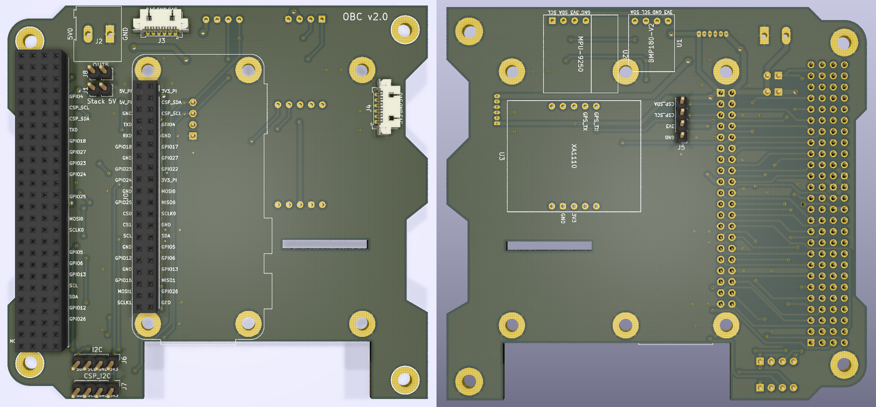
The OBC of the radiosonde consists on a PC104 PCB board compatible with the design specification of the SUCHAI CubeSat. The shape of the board considers spaces to improve the cable management inside the radiosonde. The board has some socket pins to connect either a Raspberry Pi 3, 4 or Zero. There are also some sockets to connect sensors such as the BMP180 to measure temperature and pressure, the MPU-9250 to measure the attitude of the radiosonde and a XA1110 to obtain GPS and GLONASS data.
The PCB has some pin headers to select the power source from the stack. It also has 2 I2C pins to connect additional sensors or for debug. There is also a hole to pass the ribon cable of the camera to connect it to the Raspberry Pi.
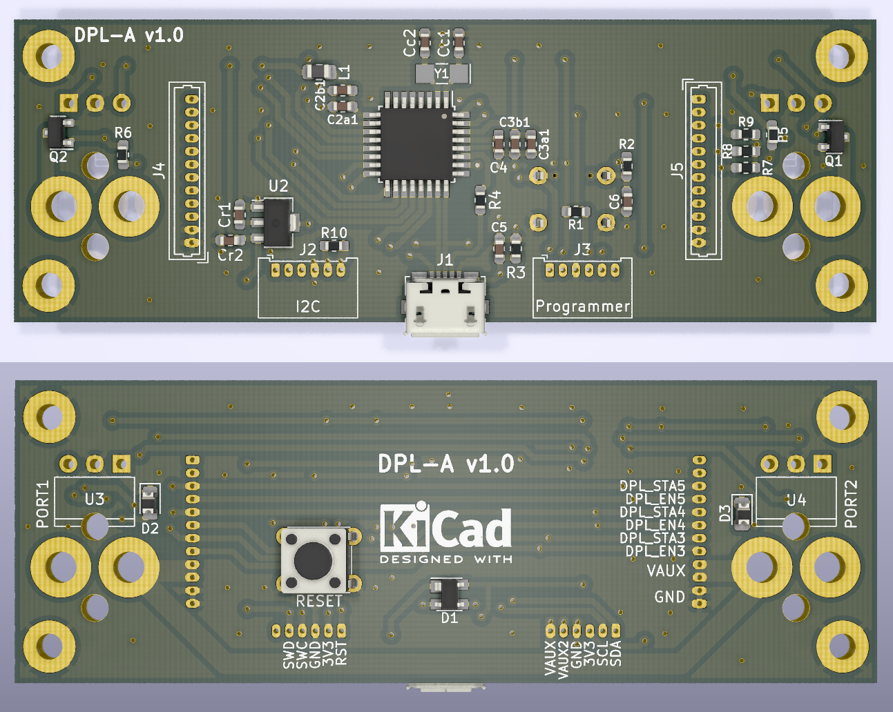
The deployment system, also called release system, consists on using Nichrome wire to cut the thread that ties the balloon with the radiosonde's structure. This thread is normally pressing a hinge lever, which is used to detect the release status. The microcontroller can detect the current status by measuring the hinge level's voltage on one of its pins. When the microcontroller receives a command to cut the string, it polarize a mosfet transistor to pass current through the Nichrome wire.
This boards has two independent ports to release balloons. Each one with a LED for the deployment status.It also has a reset button accessible from outside the main structure.
The board is designed with the shape of a type A interstage panel like the one that CubeSats of 2U ore more can have. This saves space inside the structure and enables the compatibility with both radiosondes and CubeSats.
| Qty | Value | Footprint | References |
|---|---|---|---|
| 5 | 330 | Resistors_SMD:R_0603_HandSoldering | R2, R4, R5, R6, R8 |
| 4 | 0.1uF | Capacitors_SMD:C_0603_HandSoldering | C3, C4, C5, C6 |
| 4 | 100k | Resistors_SMD:R_0603_HandSoldering | R3, R9, R10, R11 |
| 4 | Conn_01x04_UART | Pin_Headers:Pin_Header_Straight_1x04_Pitch2.54mm | J22, J23, J24, J25 |
| 3 | Conn_01x03_Male | Connectors_Molex:Molex_PicoBlade_53261-0371_03x1.25mm_Angled | J31, J32, J33 |
| 3 | Conn_01x06_Male | Connectors_Molex:Molex_PicoBlade_53261-0671_06x1.25mm_Angled | J44, J45, J46 |
| 2 | 15pF | Capacitors_SMD:C_0603_HandSoldering | C1, C2 |
| 2 | Conn_01x04_MPU-9290 | Pin_Headers:Pin_Header_Straight_1x04_Pitch2.54mm | J37, J41 |
| 2 | Conn_01x04_Male | Connectors_Molex:Molex_PicoBlade_53261-0471_04x1.25mm_Angled | J26, J29 |
| 1 | 1.0uF | Capacitors_SMD:C_0603_HandSoldering | C7 |
| 1 | 10k | Resistors_SMD:R_0603_HandSoldering | R1 |
| 1 | 2.2uF | Capacitors_SMD:C_0603_HandSoldering | C8 |
| 1 | 2.5A / 30V | TO_SOT_Packages_SMD:SOT-23 | e1 |
| 1 | 2N7002 | TO_SOT_Packages_SMD:SOT-23 | Q1 |
| 1 | 32.768 kHz | Crystals:Crystal_SMD_3215-2pin_3.2x1.5mm | Y1 |
| 1 | 47k | Resistors_SMD:R_0603_HandSoldering | R7 |
| 1 | 74AHC1G125 | TO_SOT_Packages_SMD:SOT-23-5_HandSoldering | U3 |
| 1 | AP2112K-3.3 | TO_SOT_Packages_SMD:SOT-23-5_HandSoldering | U4 |
| 1 | ATSAMD21G18A-AUT | Housings_QFP:TQFP-48_7x7mm_Pitch0.5mm | U2 |
| 1 | BAT_JUMPER | Pin_Headers:Pin_Header_Straight_1x02_Pitch2.54mm | J1 |
| 1 | BLUE | LEDs:LED_0603_HandSoldering | D1 |
| 1 | Conn_01x04_BME280 | Pin_Headers:Pin_Header_Straight_1x04_Pitch2.54mm | J40 |
| 1 | Conn_01x04_BMP180 | Pin_Headers:Pin_Header_Straight_1x04_Pitch2.54mm | J39 |
| 1 | Conn_01x04_GPS | Pin_Headers:Pin_Header_Straight_1x04_Pitch2.54mm | J43 |
| 1 | Conn_01x06_Female | Pin_Headers:Pin_Header_Straight_1x06_Pitch2.54mm | J38 |
| 1 | Conn_01x06_Male_Bootloader | Pin_Headers:Pin_Header_Straight_1x06_Pitch2.54mm | J17 |
| 1 | Conn_01x08_Female | RF_Modules:nRF24L01_Breakout | J19 |
| 1 | Conn_01x08_Male | Connectors_Molex:Molex_PicoBlade_53261-0871_08x1.25mm_Angled | J21 |
| 1 | FB - 30 Ohm | Resistors_SMD:R_0603_HandSoldering | L1 |
| 1 | GREEN | LEDs:LED_0603_HandSoldering | D3 |
| 1 | Jumper EPS VBAT | Pin_Headers:Pin_Header_Straight_1x02_Pitch2.54mm | J11 |
| 1 | Jumper LEDs 3V3 | Pin_Headers:Pin_Header_Straight_1x02_Pitch2.54mm | J13 |
| 1 | Jumper OBC 3V3 | Pin_Headers:Pin_Header_Straight_1x02_Pitch2.54mm | J9 |
| 1 | Jumper OBC Vin | Pin_Headers:Pin_Header_Straight_1x02_Pitch2.54mm | J10 |
| 1 | Jumper USB 3V3 | Pin_Headers:Pin_Header_Straight_1x02_Pitch2.54mm | J15 |
| 1 | Jumper VSTK VBAT | Pin_Headers:Pin_Header_Straight_1x02_Pitch2.54mm | J12 |
| 1 | Micro_SD_Card | Connectors:microSD_Card_Receptacle_Wuerth_693072010801 | J36 |
| 1 | Payload | Payload:PC104-Standard | U1 |
| 1 | Polyfuse_Small | Resistors_SMD:R_0603_HandSoldering | F1 |
| 1 | RED | LEDs:LED_0603_HandSoldering | D2 |
| 1 | SW_Push | Buttons_Switches_SMD:SW_SPST_B3SL-1022P | SW1 |
| 1 | USB_B_Micro | Connectors_USB:USB_Micro-B_Molex_47346-0001 | J8 |
| 1 | Vin | Connectors_Molex:Molex_PicoBlade_53261-0271_02x1.25mm_Angled | J14 |
| 1 | Vin 3v3 | Connectors_Molex:Molex_PicoBlade_53261-0271_02x1.25mm_Angled | J16 |
| 1 | YELLOW | LEDs:LED_0603_HandSoldering | D4 |
The 65 most common of 67 parts.
spel-uchile/balloon_experiment
Radiosonde platform to develop, test and integrate payloads for the future CubeSats missions

spel-uchile/balloon_experiment
Radiosonde platform to develop, test and integrate payloads for the future CubeSats missions


LeanderU/KnockBox
Focus: PCB Design of a interactive device using SAMD51 chip

PCBench/PCBench
resolution = [0.5, 0.5] pcbfolder = '../PCBs/' pcbnames = ["1Bitsy1bitsy"] iters = 30 env = PCBRoutingEnv(resolution=resolution, pcbfolder=pcbfolder, pcbnames=pcbnames) obs, info = env.reset() for in range(iters): act =…

oomlout/oomlout_oomp_project_bot_v_2

CRImier/MyKiCad
My KiCad boards. Can't be bothered uploading individually anymore, so here you go.


jsphuebner/inverter-hardware
Eagle schematics of inverter main board, sensor boards and gate drivers

It measures 96 × 89.9 mm and has 2 copper layers, 1.6 mm thick.
67 parts, built around the 74AHC1G125GW and AP2112K-3.3. The full list of its parts is on this page, with links to each part's symbol and footprint where PCBKit's library has them.
From the spel-uchile/balloon_experiment repository on GitHub, at the commit this page was made from: the board is SENSOR_MODULE/ATmega_SAT.kicad_pcb. PCBKit opens the board in the browser, with nothing to install.
Its repository states no licence, so its author keeps all rights: ask spel-uchile before reusing the design.