Skip to the content
PCBKitNew board
2 layers80.6 × 68 mmWasd m, the printed circuit board in 3D

Split-style Pro Leverless Controller

Size
80.6 × 68 mm
Copper layers
2
Thickness
1.6 mm
Parts
18
Nets
13
Pads
69
Tracks, vias
95, 27
Pours
1
Routed
Yes
KiCad
KiCad 8.0 (file 20240108)
Created
17 Jan 2025
Updated
3 Jul 2026

Overview

Wasd m is an open-source printed circuit board by speedypotato, from the speedypotato/SplitFox-Pro repository on GitHub. It is a 2-layer board of 80.6 × 68 mm with 18 parts on 13 nets, routed with 95 tracks and 27 vias.

Its parts include 4 capacitors, 4 diodes and 1 connector.

README

README.md

SplitFox-Pro

Split-style Pro Leverless Controller

This work is licensed under a Creative Commons Attribution-NonCommercial-ShareAlike 4.0 International License.

Prototype Run For Sale @ https://www.speedylabs.us/product/splitfox-pro-split-fighting-box-pro/

What's the SplitFox Pro?

Speedy Labs introduces the SplitFox Pro - Split Fighting Box (Pro)! This is a split layout leverless controller with 18 action buttons, 6 aux buttons, and a tournament lockout switch running on GP2040-CE.

Design

When designing this, I had a few main goals in mind:

  1. Split Layout
  2. Embeddable PS Auth Dongle (non-protruding)
  3. Standard or Mixbox support
  4. USB C Daughterboard

Technically this would have been the LightFox Pro, but since I'm using choc v2 here due to the rumored discontinuation of Keychron LP Opticals it would feel wrong to call it that. Hence SplitFox Pro. The layout begins with the standard 12 button leverless layout. I then took the 4 movement buttons and shifted them out one button space, creating the basic split layout. I then added a button to each side of each thumb, as typical of many 16 button leverless layouts (except these only have one center thumb button, where SplitFox Pro has two). Similarly, I added an extra button above the punch row as it's very typical to see one here in addition to a left hand pinky button because I believe that all fingers should be able to press a button at a moment's notice.

Some smaller goals, many carried over from the LightFox:

  • Maintain acrylic top for artwork
  • Aux buttons on both sides of controller for ease of use/preference
  • OLED Display
  • Mid-frame construction

BOM

  • PCBs
    • 1x SplitFox
    • 1x wasd or wasd-m
    • 1x usb-breakout
    • 1x usb-ext (optional)
  • 1x OLED ZJY096-2864KSWEG41X
  • Acrylics (2.5mm thickness)
    • 1x splitfox-bottom
    • 1x splitfox-top or splitfox-top-m
  • CNC Aluminum (or 3D print if going for a cheaper build)
    • 1x splitfox-body
    • 1x splitfox-wasd-1_2mm or splitfox-wasd-m-1_2mm (both 1.2mm thick)
  • 2x EVA Foam Feet splitfox-foot-2mm (or silicone, but it was too expensive for a small run for me)
  • 23x m3x6 ultra low profile screws
  • 2x m3 nut
  • 18x shadow hunting switches (or any choc v2 switch)
  • Keycaps
    • 4x 28.5mm
    • 14x 22.5 or 10x 22.5 + WASD (must be low profile mx stem compatible!!)
  • Double sided mounting tape (Scotch 314H-MED is a good thickness for the oled in my tests)
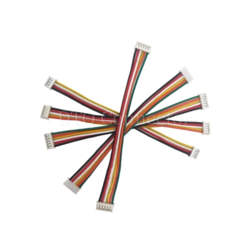
  • 2x ZH 7 Pin 10cm double headed wire (make sure you don't get the twisted cable version!! correct version e.g. https://ae01.alicdn.com/kf/S88d212727fc34138a45582e0e0a23c315.jpg)
  • 3D prints
    • 1x usb-ext-bot
    • 1x usb-ext-top
    • 1x 93657A501_Nylon Unthreaded Spacer

Optionals, but things I would include normally:

  • 1x 2mm hex wrench
  • 1x 2m usb c cable
  • 1x velcro cable tie
  • 1x zipper case
  • 1x shipping box
  • 1x honson F5

Basic Assembly Instructions

  1. Flash SplitFox pcb
  2. Plug in OLED and adhere with double sided mounting tape.
  3. Plug both ZH cable into SplitFox pcb
  4. Screw in SplitFox pcb into splitfox-body
  5. Plug WASD ZH cable into wasd pcb
  6. Screw wasd pcb into splitfox-body
  7. Put splitfox-wasd-1_2mm into topside of splitfox-body, using 93657A501_Nylon Unthreaded Spacer, 1x m3x6, and 1x m3 nut to secure and sandwich together.
  8. Insert shadow hunting switches. Support sockets from backside when inserting to avoid damage.
  9. Plug USB ZH cable into usb-breakout pcb
  10. Screw in usb-breakout pcb into splitfox-body
  11. Apply 2x splitfox-foot-2mm to splitfox-bottom
  12. Screw in splitfox-bottom to splitfox-body
  13. Add artwork cutout if desired
  14. Screw in splitfox-top to splitfox-body

Video Guides

SplitFox Pro Assembly & Mixbox Setup: https://youtu.be/-rr3WSn5i6s
SplitFox Pro LED Setup (Beta): https://youtu.be/0wB09UQQ0kg

Done! Be sure to post your builds on Discord @ https://discord.gg/MmuKd73XbY or Twitter/X and tag me @SpeedyPotato_

Known Issues

v1.1 SplitFox fixes below issue by changing back to the crystal setup I used to use. Could also be just a bad batch from v1 as I used a different PCBa for v1.1 too.

With v1, testing has gone fairly smoothly aside from one weird issue, where plugging in an auth dongle causes the controller to freeze/reboot. If you leave the dongle plugged in all the time, this isn't an issue, but I hope to root cause it someday. It might be the RP2040 crystal setup or the XC6206 being too weak, but both are also fairly tested in other controllers that don't have issues. RP2040 crystal setup is new to me but is recommended in RP2040's hardware design guide. XC6206 is used in production LightFox controllers and those have no issues hotplugging auth devices.

Parts

18
QtyValueFootprintReferences
4100nFCapacitor_SMD:C_0402_1005MetricC1, C2, C3, C4
4MountingHoleMountingHole:MountingHole_3mmH1, H2, H3, H4
4choc_SK6812MINI-EPCM_marbastlib-choc:LED_choc_6028RLED1, LED2, LED3, LED4
4choc_v1_SW_HSPCM_marbastlib-xp-choc:SW_choc_v2_HS_CPG135001S30_1uCH1, CH2, CH3, CH4
1MountingHolepocket-sdvx-pico-local:logo_smallLOGO1
1S7B-ZR-SM4A-TF(LF)(SN)_C5118704easyeda:CONN-SMD_S7B-ZR-SM4A-TF-LF-SNCN1

Questions

How big is the Wasd m PCB?

It measures 80.6 × 68 mm and has 2 copper layers, 1.6 mm thick.

What parts does the Wasd m use?

18 parts. The full list of its parts is on this page, with links to each part's symbol and footprint where PCBKit's library has them.

Where can I download the Wasd m KiCad files?

From the speedypotato/SplitFox-Pro repository on GitHub, at the commit this page was made from: the board is pcb/wasd-m/wasd-m.kicad_pcb and its schematic pcb/splitfox/splitfox.kicad_sch. PCBKit opens the board in the browser, with nothing to install.

Can I use the Wasd m design in my own project?

Its repository states no licence, so its author keeps all rights: ask speedypotato before reusing the design.

More from speedypotato/SplitFox-Pro

4
  • 2 layers255.8 × 122.5 mmSplitfox, the printed circuit board in 3D

    Splitfox

    speedypotato/SplitFox-Pro

    Split-style Pro Leverless Controller

    143 parts6
  • 2 layers80.6 × 68 mmWasd, the printed circuit board in 3D

    Wasd

    speedypotato/SplitFox-Pro

    Split-style Pro Leverless Controller

    26 parts6
  • 2 layers20 × 20 mmUsb breakout, the printed circuit board in 3D

    Usb breakout

    speedypotato/SplitFox-Pro

    Split-style Pro Leverless Controller

    7 parts6
  • 2 layers21.3 × 30.3 mmUsb ext, the printed circuit board in 3D

    Usb ext

    speedypotato/SplitFox-Pro

    Split-style Pro Leverless Controller

    4 parts6

Similar boards

  • 2 layers27.9 × 16.5 mmPowerSSO-24 breakout, the printed circuit board in 3D

    PowerSSO-24 breakout

    rusefi/rusefi

    rusefi - GPL internal combustion engine control unit

    18 parts1.2k
  • 2 layers42.7 × 13.7 mmStm32-mini12864, the printed circuit board in 3D

    Stm32-mini12864

    VoronDesign/Voron-Hardware

    Cool Hardware designed by the Voron Design group

    18 parts1.1kGPL-3.0
  • 2 layers41.2 × 46.6 mmThumb cluster left, the printed circuit board in 3D

    Thumb cluster left

    JesusFreke/lalboard

    A 3D-printed keyboard inspired by the DataHand

    18 parts993
  • 2 layers44 × 51.3 mm4272MAVcoder R4, the printed circuit board in 3D

    4272MAVcoder R4

    hackclub/OnBoard

    💡 Join 1,000 teenagers and make your first PCB with a $100 grant!

    18 parts915
  • 2 layers28.3 × 14.3 mmTap Photosensor PCB, the printed circuit board in 3D

    Tap Photosensor PCB

    VoronDesign/Voron-Tap

    Tap is a nozzle-based z-probe for the V2 and Trident printer designs. The entire toolhead moves to trigger an optical switch. Tap offers many advantages:

    18 parts716GPL-3.0
  • 2 layers20.3 × 15.2 mmL0 stepper driver, the printed circuit board in 3D

    L0 stepper driver

    Luos-io/luos_engine

    Open-source and real-time orchestrator for cyber-physical-systems, to easily design, test and deploy embedded applications and digital twins.

    18 parts546MIT
  • 2 layersMooltipass, the printed circuit board in 3D

    Mooltipass

    limpkin/mooltipass

    Github repository dedicated to the mooltipass project

    18 parts531
  • 2 layers42.5 × 28.8 mmC5VRX JACK DIY V2, the printed circuit board in 3D

    C5VRX JACK DIY V2

    Twotoz/C5VRX

    Ultra-minimal, zero-CPU 5.8 GHz analog FPV video receiver using ESP32-C5 Wi-Fi 6 PHY MODEM_DIAG, BitScrambler WBFM demodulation & resistor DAC CVBS

    18 parts515GPL-3.0