
2 layers80.6 × 68 mm
 speedypotato/SplitFox-Pro6
Split-style Pro Leverless Controller
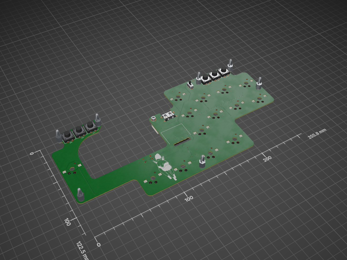
Splitfox is an open-source printed circuit board by speedypotato, from the speedypotato/SplitFox-Pro repository on GitHub. It is a 2-layer board of 255.8 × 122.5 mm with 143 parts on 102 nets, routed with 1,125 tracks and 232 vias.
It is built around the RP2040, W25Q128JVSIQ and SN74LV1T34DBVR-TP, with the USBLC6-2SC6, SK6812MINI-E and GT-TC152A-H085-L1 among its other parts. Its parts include 54 capacitors, 29 diodes, 14 resistors, 8 switches and 5 ICs. It belongs with the RP2040 boards of this library.


Split-style Pro Leverless Controller
Speedy Labs introduces the SplitFox Pro - Split Fighting Box (Pro)! This is a split layout leverless controller with 18 action buttons, 6 aux buttons, and a tournament lockout switch running on GP2040-CE.
When designing this, I had a few main goals in mind:
Technically this would have been the LightFox Pro, but since I'm using choc v2 here due to the rumored discontinuation of Keychron LP Opticals it would feel wrong to call it that. Hence SplitFox Pro. The layout begins with the standard 12 button leverless layout. I then took the 4 movement buttons and shifted them out one button space, creating the basic split layout. I then added a button to each side of each thumb, as typical of many 16 button leverless layouts (except these only have one center thumb button, where SplitFox Pro has two). Similarly, I added an extra button above the punch row as it's very typical to see one here in addition to a left hand pinky button because I believe that all fingers should be able to press a button at a moment's notice.
Some smaller goals, many carried over from the LightFox:
Optionals, but things I would include normally:
SplitFox Pro Assembly & Mixbox Setup: https://youtu.be/-rr3WSn5i6s
SplitFox Pro LED Setup (Beta): https://youtu.be/0wB09UQQ0kg
Done! Be sure to post your builds on Discord @ https://discord.gg/MmuKd73XbY or Twitter/X and tag me @SpeedyPotato_
v1.1 SplitFox fixes below issue by changing back to the crystal setup I used to use. Could also be just a bad batch from v1 as I used a different PCBa for v1.1 too.
With v1, testing has gone fairly smoothly aside from one weird issue, where plugging in an auth dongle causes the controller to freeze/reboot. If you leave the dongle plugged in all the time, this isn't an issue, but I hope to root cause it someday. It might be the RP2040 crystal setup or the XC6206 being too weak, but both are also fairly tested in other controllers that don't have issues. RP2040 crystal setup is new to me but is recommended in RP2040's hardware design guide. XC6206 is used in production LightFox controllers and those have no issues hotplugging auth devices.
| Qty | Value | Footprint | References |
|---|---|---|---|
| 41 | 100nF | Capacitor_SMD:C_0402_1005Metric | C1, C3, C10, C13, C16, C18, C19, C20, C21, C24, C25, C26, C27, C28, C29, C30 +25 |
| 28 | SK6812MINI-E | PCM_marbastlib-various:LED_6028R | LED1, LED2, LED10, LED11, LED12, LED13, LED14, LED15, LED16, LED17, LED18, LED19, LED20, LED21, LED22, LED23 +12 |
| 14 | choc_v1_SW_HS | PCM_marbastlib-xp-choc:SW_choc_v2_HS_CPG135001S30_1u | CH1, CH2, CH3, CH4, CH5, CH6, CH7, CH8, CH9, CH10, CH11, CH12, CH13, CH14 |
| 8 | 1uF | Capacitor_SMD:C_0402_1005Metric | C2, C4, C5, C9, C11, C12, C14, C15 |
| 7 | MountingHole | MountingHole:MountingHole_3mm | H1, H2, H3, H4, H5, H6, H7 |
| 6 | GT-TC152A-H085-L1 | easyeda:SW-TH_4P-L12.0-W12.0-P5.00-LS12.5 | SW3, SW4, SW5, SW6, SW7, SW8 |
| 4 | 27R | Resistor_SMD:R_0402_1005Metric | R1, R2, R3, R4 |
| 3 | 500mA | Fuse:Fuse_1206_3216Metric | F1, F2, F3 |
| 2 | 10k | Resistor_SMD:R_0402_1005Metric | R8, R9 |
| 2 | 1k | Resistor_SMD:R_0402_1005Metric | R5, R6 |
| 2 | 30pF | Capacitor_SMD:C_0402_1005Metric | C6, C7 |
| 2 | 4.7uF | Capacitor_SMD:C_0402_1005Metric | C17, C22 |
| 2 | 5k1 | Resistor_SMD:R_0402_1005Metric | R13, R14 |
| 2 | S7B-ZR-SM4A-TF(LF)(SN)_C5118704 | easyeda:CONN-SMD_S7B-ZR-SM4A-TF-LF-SN | CN1, CN2 |
| 1 | 0.5-30P XJH2.0 043 | easyeda:FPC-SMD_30P-P0.50_0.5-30P-XJH2.0-043 | FPC1 |
| 1 | 12MHz | Crystal:Crystal_SMD_3225-4Pin_3.2x2.5mm | Y1 |
| 1 | 2.2uF | Capacitor_SMD:C_0402_1005Metric | C23 |
| 1 | 4.7M | Resistor_SMD:R_0402_1005Metric | R12 |
| 1 | 470R | Resistor_SMD:R_0402_1005Metric | R11 |
| 1 | 4K7 | Resistor_SMD:R_0402_1005Metric | R7 |
| 1 | 910K | Resistor_SMD:R_0402_1005Metric | R10 |
| 1 | ESD | Diode_SMD:D_SOD-123 | D1 |
| 1 | MountingHole_Pad | MountingHole:MountingHole_3mm_Pad | H8 |
| 1 | PicoFox | PicoFoxpretty:picofox_small | LOGO2 |
| 1 | RP2040 | Footprints:RP2040-QFN-56 | U1 |
| 1 | SN74LV1T34DBVR | easyeda:SOT-23-5_L2.9-W1.6-P0.95-LS2.8-BR | U2 |
| 1 | SS-12D07-L5-B | easyeda:SW-TH_SS-12D07-X-X | SW2 |
| 1 | SpeedyLabs | pocket-sdvx-pico-local:logo | LOGO1 |
| 1 | TS24CA | easyeda:SW-SMD_TS24CA | SW1 |
| 1 | TYPE-C-31-M-12 | easyeda:USB-C_SMD-TYPE-C-31-M-12 | USBC1 |
| 1 | USB-AF-90-10X15.7-H5.72-CB | easyeda:USB-A-SMD_C41014 | USB1 |
| 1 | USBLC6-2SC6 | Package_TO_SOT_SMD:SOT-23-6 | U5 |
| 1 | W25Q128JVS | Package_SO:SOIC-8_5.23x5.23mm_P1.27mm | U3 |
| 1 | XC6206PxxxMR-Regulator_Linear | Package_TO_SOT_SMD:SOT-23 | U4 |
It measures 255.8 × 122.5 mm and has 2 copper layers, 1.2 mm thick.
143 parts, built around the RP2040, W25Q128JVSIQ, SN74LV1T34DBVR-TP and USBLC6-2SC6. The full list of its parts is on this page, with links to each part's symbol and footprint where PCBKit's library has them.
From the speedypotato/SplitFox-Pro repository on GitHub, at the commit this page was made from: the board is pcb/splitfox/splitfox.kicad_pcb and its schematic pcb/splitfox/splitfox.kicad_sch. PCBKit opens the board in the browser, with nothing to install.
Its repository states no licence, so its author keeps all rights: ask speedypotato before reusing the design.


azais-corentin/espion
Multi-camera IR marker tracking: ESP32-P4/C5 firmware, Rust host, KiCad hardware


tyevco/dial-me-spinner
A Bluetooth dial spinner about 70 mm across, built on the nRF52840. A heavy, balanced stainless flywheel ring spins around a stationary centre that holds a colour OLED and a ring of 48 addressable RGB LEDs.

CubeShifter/Duck
A little fidget toy that lets you click a keyboard switch and plays a noise.


