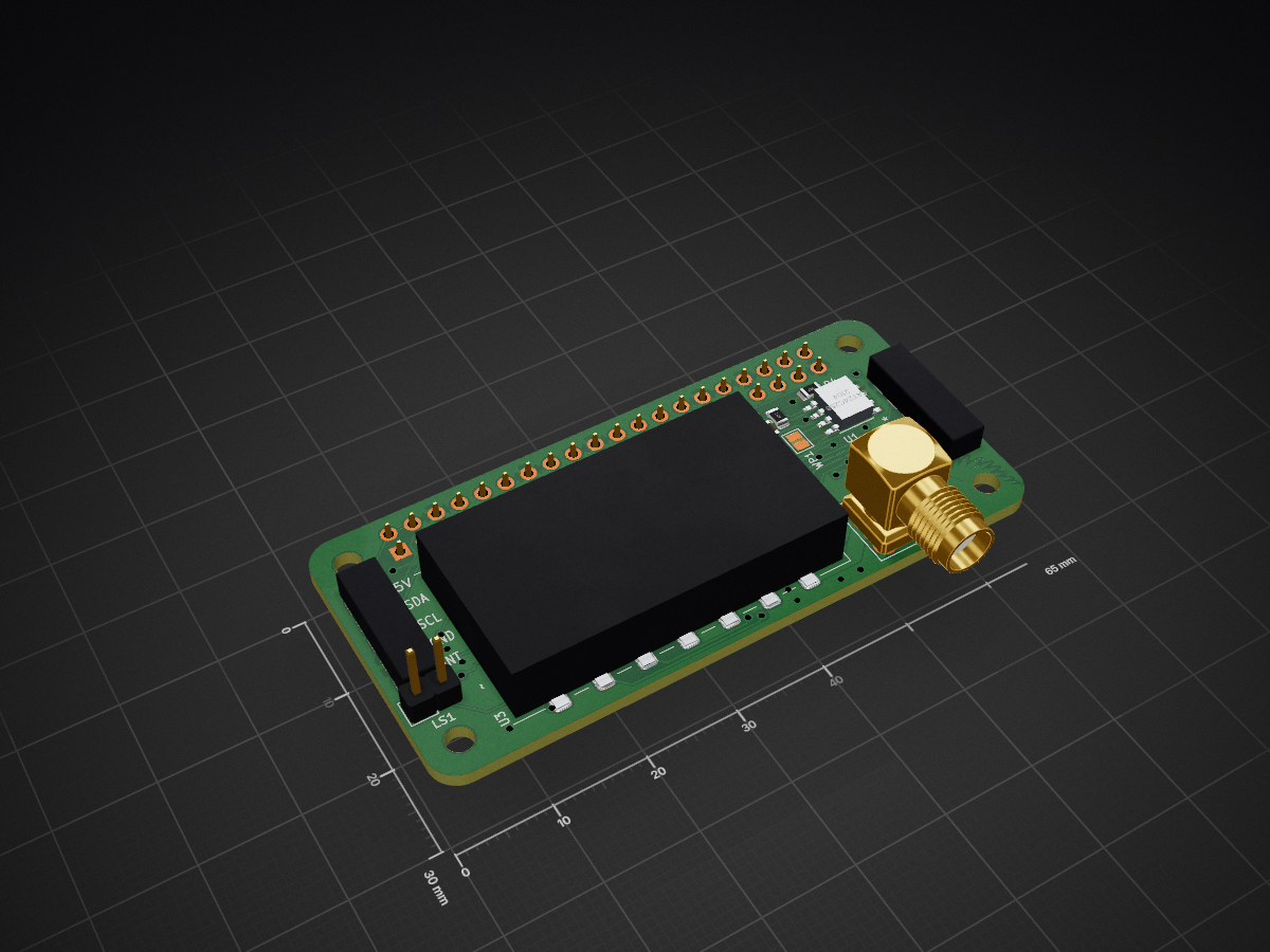
Mohawk is an open-source printed circuit board by sparques, from the sparques/mohawk repository on GitHub, published under the GPL-2.0 licence. It is a 2-layer board of 65 × 30 mm with 61 parts on 99 nets, routed with 667 tracks and 107 vias.
It is built around the MAX232N, TLV320AIC3204IRHBR and CAT24C256LI, with the ASE-18.432MHZ-LC-T among its other parts. Its parts include 19 resistors, 18 capacitors, 6 ICs, 5 connectors and 1 diode. It belongs with the radio and wireless boards of this library.
Mohawk is a Raspberry Pi Zero µHAT-sized UHF/VHF radio interface built around a DRA818 radio module which comes in a UHF and a VHF variant (DRA818U / DRA818V). It brings the radio's audio, configuration UART, and push-to-talk control to a Raspberry Pi, and provides an RS-232 port for an external device. The current design is a KiCad 10 schematic and two-layer PCB. Hardware validation has not been recorded in this repository.
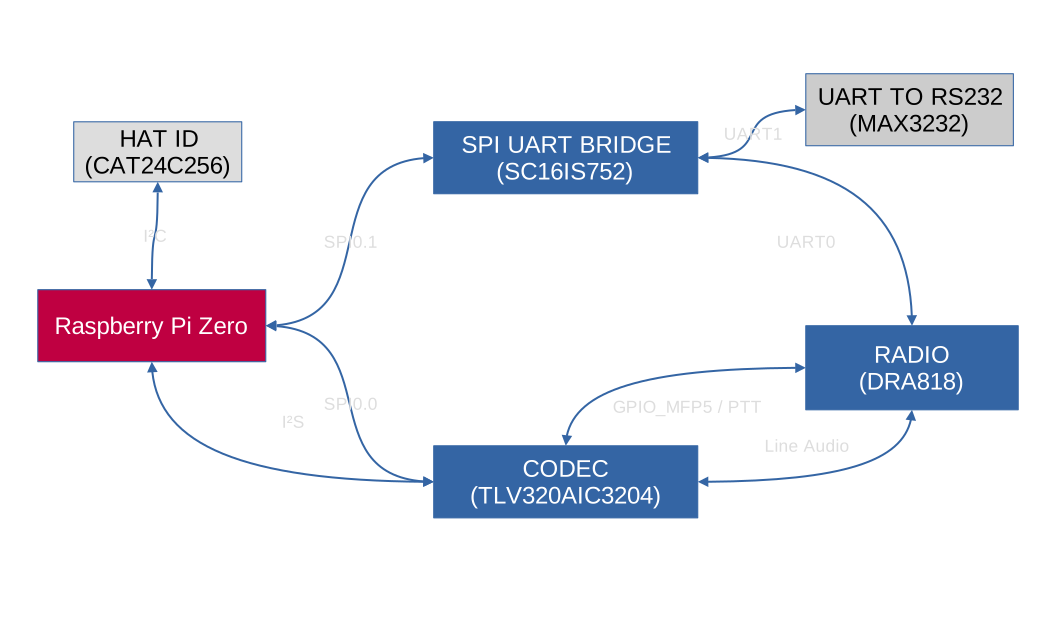
Linux has drivers for both the SPI UART interface and the codec, so two hardware TTYs show up and the codec shows up as a regular alsa soundcard.
The BoM will be finalized once a verified working prototype has been assembled and specific part variants have been nailed down and confirmed good.
The Pi's SPI0 bus is shared by the UART bridge (CE1) and codec (CE0). The codec's digital audio uses the Pi's PCM/I²S pins. The bridge's two UART channels connect separately to the DRA818 and MAX3232, leaving the Pi's built-in UART pins available on the 40-pin header. The codec connects to the radio's analog input and output; its GPIO_MFP5 pin drives the radio's PTT net. The codec's right headphone output feeds the two-pin speaker connection through a coupling capacitor.
Functional Diagram
External connections
Pin numbers below come from the current schematic/netlist. Check the PCB pad numbering and your cable orientation before attaching hardware.
Connector
Connection
J1
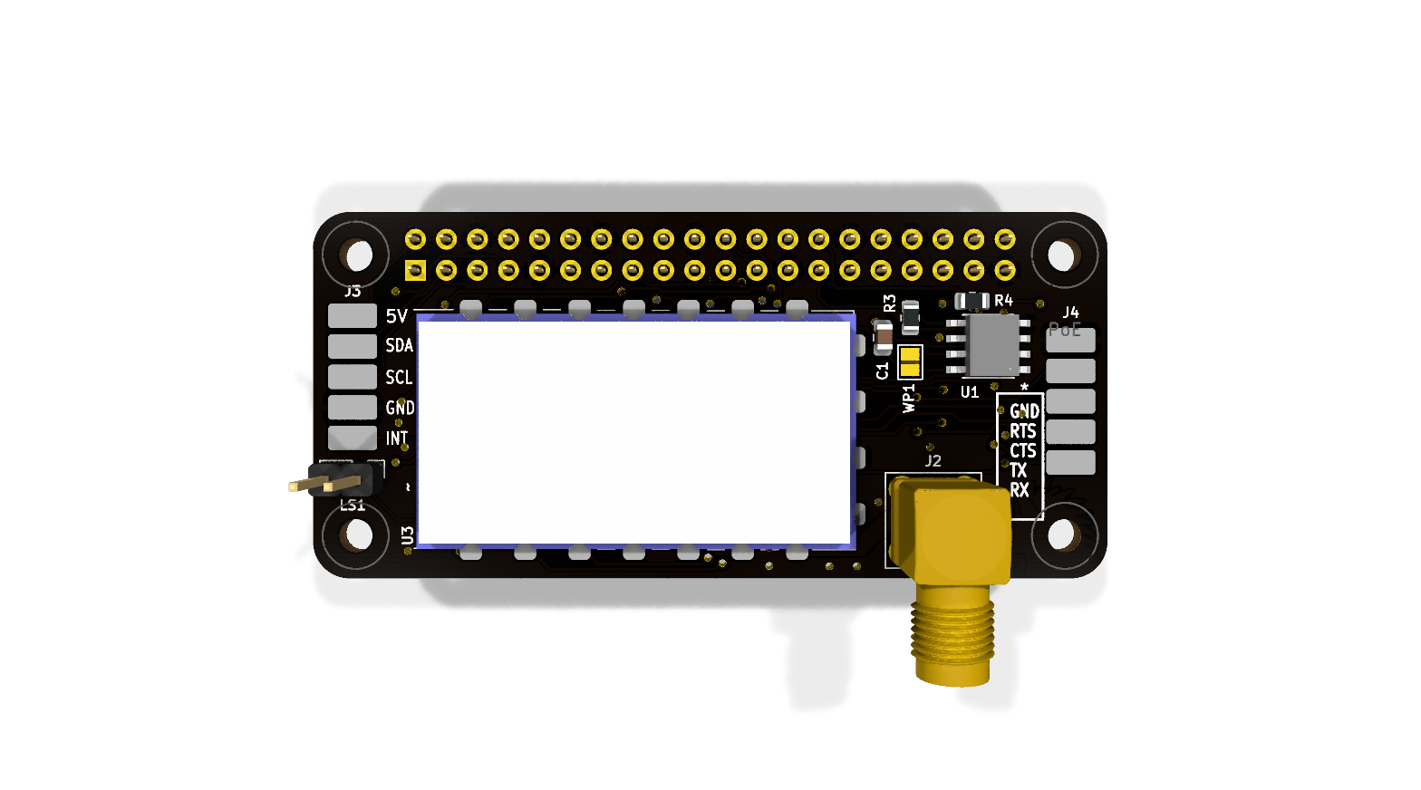
2 × 20 Raspberry Pi GPIO socket; supplies 5 V and 3.3 V and carries SPI0, PCM/I²S, I²C, and control GPIOs.
J2
SMA antenna connector wired to the DRA818 ANT pin.
J3
Five SMD pads for a UI board: 1 GPIO17, 2 GND, 3 GPIO3/SCL1, 4 GPIO2/SDA1, 5 +5 V.
J4
Five SMD pads labeled “DB9 Header”: 1 RS232_RX, 2 RS232_TX, 3 RS232_CTS, 4 RS232_RTS, 5 GND. An external cable/connector is needed for a DB9 interface.
LS1
Two-pin speaker header: codec headphone output via C18 and GND.
WP1
Open solder jumper for EEPROM write protection; closing it connects the EEPROM's WP pin to 3.3 V.
J3 carries 5 V power but uses the Pi's 3.3 V GPIO/I²C signals. GPIO17 Is brought out for use as an interrupt, but is just a GPIO pin, so it could be used for an idicator LED or a button, etc. Use the netlist/pin table above when wiring a UI board.
There is no USB UART or 2 × 5 IDC RS-232 connector in the current schematic. The external serial connection is the MAX3232 and J4's five SMD pads.
The HAT ID EEPROM uses ID_SDA/ID_SCL on J1 pins 27/28. Those are separate from the ordinary I²C1 pins used at J3. The Device Tree overlay is present but has not been tested on hardware.
Control signals on the Pi header
Pi GPIO (physical pin)
Connected function
GPIO5 (29)
SC16IS752 reset
GPIO7 / SPI0 CE1 (26)
SC16IS752 chip select
GPIO8 / SPI0 CE0 (24)
TLV320AIC3204 chip select
GPIO18–21 (12, 35, 38, 40)
Codec bit clock, word clock, data to Pi, and data from Pi
GPIO22 (15)
DRA818 power-down (PD)
GPIO23 (16)
DRA818 squelch (SQ)
GPIO25 (22)
SC16IS752 interrupt
GPIO27 (13)
Codec reset
The radio's PTT is connected to the codec's multifunction GPIO rather than directly to a Pi GPIO. Software must configure that codec pin before attempting to transmit. These are schematic connections, not a tested Linux setup or a promise of a particular /dev/tty* assignment.
Device Tree overlay
The overlay targets the Raspberry Pi Zero family. It enables SPI0 with the codec on CE0 and the SC16IS752 on CE1, enables I²S, and creates a simple ALSA sound card. UART channel A connects to the DRA818; channel B connects to the MAX3232. The bridge's interrupt and reset use GPIO25 and GPIO5. The codec reset uses GPIO27.
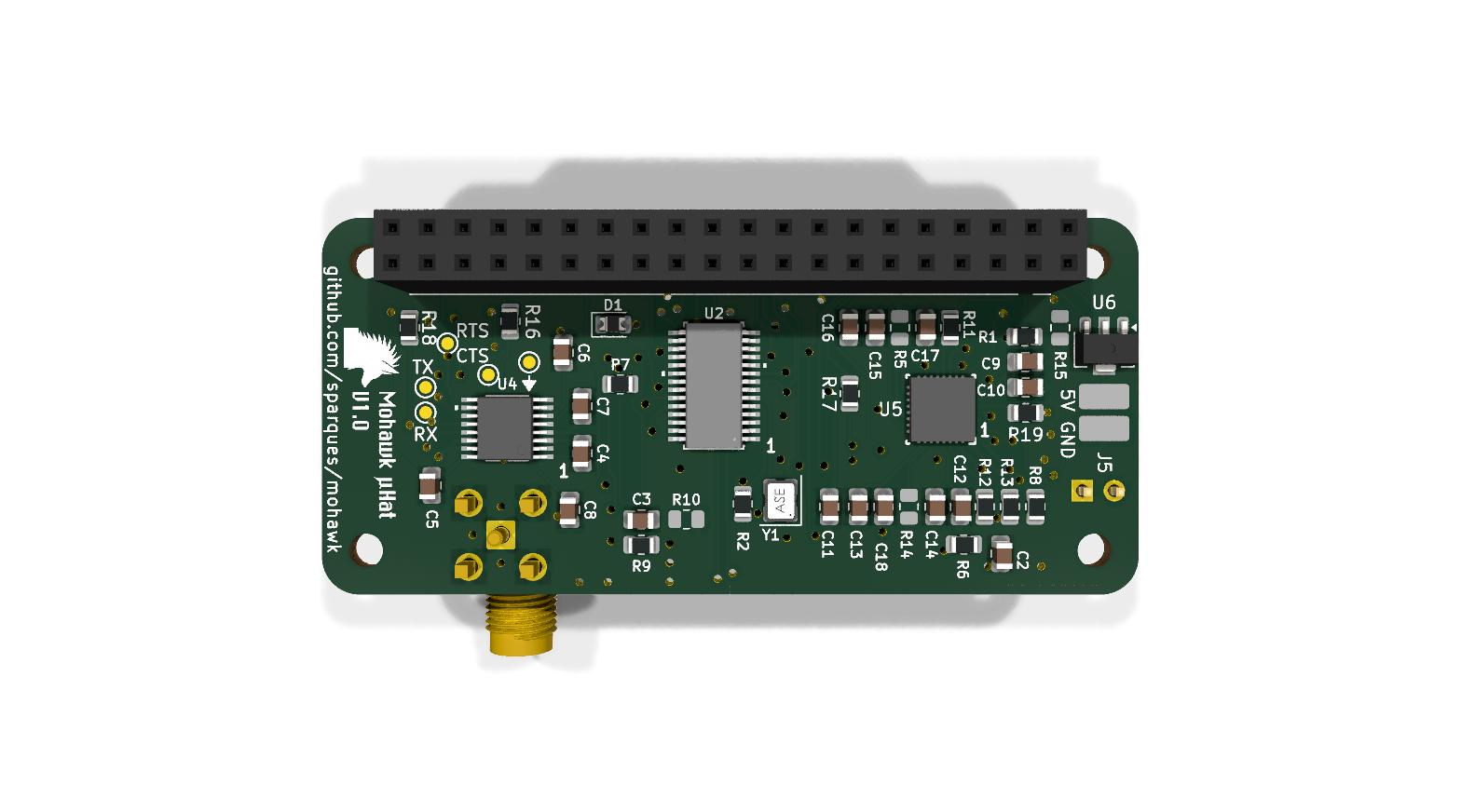
Fit R15 (10 Ω) before using the codec. The schematic marks it do-not-populate, but it is the only connection from GPIO4/GPCLK0 to the codec MCLK pin. The overlay supplies a 12.288 MHz master clock on that pin. With R15 absent, the audio clock is disconnected regardless of Device Tree configuration.
On a Raspberry Pi with the kernel Device Tree headers installed, compile and install the overlay:
Add dtoverlay=mohawk to /boot/firmware/config.txt and reboot. On systems using /boot/overlays and /boot/config.txt, use those paths instead. The HAT ID EEPROM is not programmed by this overlay; add the dtoverlay line explicitly until it is.
The codec's MFP5 pin is initialized high so the radio's active-low PTT stays released. Its ALSA MFP5 GPIO control can later drive it low to transmit; ensure the control is set high again when transmission ends. The overlay also describes the radio receive audio on IN1_L, transmit audio on LOL, and the monitor headphone output on HPR. Audio mixer routing and levels still need to be set in ALSA and verified on a prototype.
Design and build status
The PCB is routed in the saved design, and KiCad reports no unconnected items. A KiCad 10 check of this checkout found 26 ERC violations, 59 PCB DRC violations, and two schematic/PCB footprint-name parity warnings. The DRC findings include silk overlap, copper-to-edge and hole-clearance errors, alongside warnings about copper islands, dangling copper, footprint library matches, and text thickness. Review and resolve the reports in KiCad before ordering boards. The schematic also marks R5, R10, R14, and R15 as do-not-populate.
To rerun the checks and export a BOM from the project root:
U1 (the I²C EEPROM) and U4 (MAX3232) are technically optional. You do not need the MAX32322 or its supporting passives if you do not need RS-232 support. The I2C EEPROM lets a DeviceTree overlay be automatically loaded at boot so linux kernel modules know what the pin assignments are, but this is just a convenience and also not strictly required.
Legal Notice
Neither this device nor the DRA818 module is, obviously, certified by the FCC. Only a suitably licensed individual may transmit using this device: you must have an amateur radio license. It is up to the operator to ensure they are following FCC requirements.
It measures 65 × 30 mm and has 2 copper layers, 1.6 mm thick.
What parts does the Mohawk use?
61 parts, built around the MAX232N, TLV320AIC3204IRHBR, CAT24C256LI and ASE-18.432MHZ-LC-T. The full list of its parts is on this page, with links to each part's symbol and footprint where PCBKit's library has them.
Where can I download the Mohawk KiCad files?
From the sparques/mohawk repository on GitHub, at the commit this page was made from: the board is mohawk/mohawk.kicad_pcb and its schematic mohawk/mohawk.kicad_sch. PCBKit opens the board in the browser, with nothing to install.
Can I use the Mohawk design in my own project?
Its repository publishes it under the GPL-2.0 licence: you may reuse it on that licence's terms (keep the author's notice, and for a copyleft licence share your changes alike).
Aarebot is a dynamic realtime sampler built as a Eurorack module. At its core is a stereo tape-style engine with a hot-swapping record/playback buffer - this enables to record and play simultaneously.