4 layers48.5 × 56 mm
Digirig icom
1vers1on/digirig_icom
A custom hardware controller for the ICOM IC-2730 radio, featuring digital audio processing and USB connectivity.
70 parts1

 95lux/aware0115
Aarebot is a dynamic realtime sampler built as a Eurorack module. At its core is a stereo tape-style engine with a hot-swapping record/playback buffer - this enables to record and play simultaneously.
Aware01 h7 rev2 0 is an open-source printed circuit board by 95lux, from the 95lux/aware01 repository on GitHub, published under the GPL-3.0 licence. It is a 4-layer board of 46 × 110 mm with 158 parts on 134 nets, routed with 1,213 tracks and 242 vias.
It is built around the OPA2322AIDRGR, LMR50410Y5FQDBVRQ1 and TLV320AIC3204IRHBR, with the LM1117MP-3.3, LM4040DIM3X-10 and MMBT3904 among its other parts. Its parts include 61 capacitors, 43 resistors, 18 ICs, 14 connectors and 7 diodes. It belongs with the STM32 boards of this library.


Dynamic realtime stereo sampler for Eurorack modular synthesizer - STM32H7
Aarebot is a dynamic realtime sampler built as a Eurorack module. At its core is a stereo tape-style engine with a hot-swapping record/playback buffer - this enables to record and play simultaneously. Slicing markers can be added on the fly, and processing through an onboard effects chain.
Samplerate decimation trades fidelity for buffer length. A Schroeder reverb implementation reaching from spacious room to sharp metallic resonance ringing depending on the XY effect mapping.
More DSP FX and taillred XY mapping is on the way and will turn Aarebot into an IDM LOFI crunch machine.
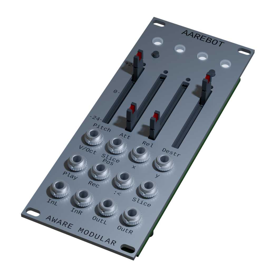
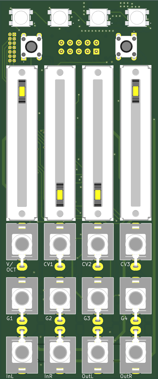
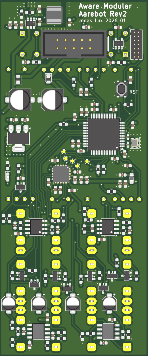
| Interface | Function |
|---|---|
| Pot 1 | Base pitch (±24 semitones) |
| Pot 2 | Envelope attack |
| Pot 3 | Envelope decay / release |
| Pot 4 | Recording decimation |
| V/Oct | Pitch CV input |
| CV 2 | XY effect plane - X axis |
| CV 3 | XY effect plane - Y axis |
| Gate 1 | Record |
| Gate 2 | Play |
| Gate 3 | (unassigned) |
| Gate 4 | Set slice marker |
├── firmware/                 STM32CubeMX project and C source
|   ├── Aware                 Main firmware implementation
|   └── Src                   CubeMX generated src files
├── hardware/
│   ├── aware01_h7_rev2_0/    KiCad schematic and PCB
│   └── simulation/           SPICE simulations for analog stages
└── docs/
    ├── images/               PCB renders and oscilloscope captures
    ├── ba/                   Bachelor thesis
    │   ├── latex/            LaTeX source files
    │   ├── images/           Figures and plots
    │   ├── diagrams/         DrawIO block diagrams
    │   └── scripts/          Python scripts for analysis and plots
    └── project_management/   Project planning documents
        ├── lastenheft.tex    Requirements specification
        ├── pflichtenheft.tex Functional specification
└── projectplan.tex Project plan| Tool | Arch | Debian/Ubuntu |
|---|---|---|
| ARM cross-compiler | arm-none-eabi-gcc | gcc-arm-none-eabi |
| ARM newlib | arm-none-eabi-newlib | libnewlib-arm-none-eabi |
| CMake ≥ 3.22 | cmake | cmake |
| Ninja | ninja | ninja-build |
cd firmware

# Configure + build (Debug)
cmake --preset Debug
cmake --build --preset Debug

# Configure + build (Release)
cmake --preset Release
cmake --build --preset Release
The output ELF is at firmware/build/Debug/firmware.elf.
Requires an ST-Link probe. Either st-flash (stlink) or openocd can be used.
openocd (recommended; works directly with ELF):
openocd -f interface/stlink.cfg -f target/stm32h7x.cfg \
  -c "program firmware/build/Debug/firmware.elf verify reset exit"
st-flash (requires converting ELF to binary first):
arm-none-eabi-objcopy -O binary \
  firmware/build/Debug/firmware.elf \
  firmware/build/Debug/firmware.bin

st-flash write firmware/build/Debug/firmware.bin 0x8000000| Tool | Arch | Debian/Ubuntu |
|---|---|---|
| openocd | openocd | openocd |
| st-flash | stlink | stlink-tools |
Designed in KiCad. The hardware directory contains the full schematic, PCB layout, and SPICE simulations for the analog input and output conditioning stages.
Opening the KiCad project requires the custom component library. Clone it alongside this repo:
git clone https://github.com/95lux/kicad_libraryThen add it as a global library in KiCad: Preferences → Manage Symbol Libraries (and Manage Footprint Libraries), pointing to the cloned directory.
| Parameter | Value |
|---|---|
| Sample rate | 48 kHz |
| Bit depth | 16-bit |
| Recording buffer | 2.5 s (stereo) |
| End-to-end latency | ~1.9 ms |
| Audio codec | TLV320AIC3204 |
| Parameter | Value |
|---|---|
| MCU | STM32H7A3RITx (Cortex-M7, 280 MHz) |
| Form factor | 10 HP, 3U Eurorack |
| Audio I/O levels | ±5 V |
| CV input range | ±10 V |
| V/Oct range | −1.5 V to +5 V |
| Power (+12V) | ~80 mA idle, ~140 mA peak |
| Power (−12V) | ~20 mA |
| Component | License |
|---|---|
| Firmware / software | GPL-3.0 |
| Hardware (schematics, PCB, SPICE) | CERN OHL-S v2 |
| Thesis / documentation | CC BY 4.0 |
| Qty | Value | Footprint | References |
|---|---|---|---|
| 32 | 100n | Capacitor_SMD:C_0603_1608Metric | C3, C10, C11, C12, C20, C24, C25, C26, C27, C28, C29, C30, C31, C32, C33, C34 +16 |
| 8 | 100k | Resistor_SMD:R_0603_1608Metric_Pad0.98x0.95mm_HandSolder | R24, R25, R26, R27, R33, R35, R39, R41 |
| 7 | 10k | Resistor_SMD:R_0603_1608Metric_Pad0.98x0.95mm_HandSolder | R4, R8, R9, R28, R29, R30, R31 |
| 7 | 10u | Capacitor_SMD:C_0603_1608Metric | C4, C8, C9, C13, C41, C42, C44 |
| 5 | TestPoint | TestPoint:TestPoint_Pad_D1.0mm | TP1, TP2, TP3, TP4, TP5 |
| 4 | 10k | Eurorack:PTL30-15R1-103B2 | U6, U7, U8, U9 |
| 4 | 1n | Capacitor_SMD:C_0603_1608Metric | C57, C58, C60, C61 |
| 4 | 587-2054-127F | Eurorack:5872054127F | IC1, IC2, IC3, IC4 |
| 4 | 75 | Resistor_SMD:R_0603_1608Metric_Pad0.98x0.95mm_HandSolder | R10, R11, R12, R13 |
| 4 | MMBT3904 | Package_TO_SOT_SMD:SOT-23 | Q1, Q2, Q3, Q4 |
| 3 | 1k | Resistor_SMD:R_0603_1608Metric_Pad0.98x0.95mm_HandSolder | R1, R22, R23 |
| 3 | 1u | Capacitor_SMD:C_0603_1608Metric | C18, C22, C43 |
| 3 | 2.2u | Capacitor_SMD:C_0603_1608Metric | C2, C19, C23 |
| 3 | 200k | Resistor_SMD:R_0603_1608Metric_Pad0.98x0.95mm_HandSolder | R32, R34, R40 |
| 3 | 33k | Resistor_SMD:R_0603_1608Metric_Pad0.98x0.95mm_HandSolder | R36, R37, R43 |
| 2 | 1.8k | Resistor_SMD:R_0603_1608Metric_Pad0.98x0.95mm_HandSolder | R16, R17 |
| 2 | 10u | Capacitor_SMD:CP_Elec_4x5.4 | C52, C53 |
| 2 | 12k | Resistor_SMD:R_0603_1608Metric_Pad0.98x0.95mm_HandSolder | R14, R15 |
| 2 | 14pF | Capacitor_SMD:C_0402_1005Metric_Pad0.74x0.62mm_HandSolder | C17, C21 |
| 2 | 18p | Capacitor_SMD:C_0603_1608Metric | C54, C55 |
| 2 | 2.2u | Capacitor_SMD:CP_Elec_4x5.4 | C48, C49 |
| 2 | 39k | Resistor_SMD:R_0603_1608Metric_Pad0.98x0.95mm_HandSolder | R20, R21 |
| 2 | 4.7k | Resistor_SMD:R_0603_1608Metric_Pad0.98x0.95mm_HandSolder | R5, R6 |
| 2 | 47u | Capacitor_SMD:CP_Elec_6.3x5.9 | C14, C15 |
| 2 | 5.6k | Resistor_SMD:R_0603_1608Metric_Pad0.98x0.95mm_HandSolder | R18, R19 |
| 2 | BAT54A | Package_TO_SOT_SMD:SOT-23 | D6, D7 |
| 2 | BAT54S | Package_TO_SOT_SMD:SOT-23 | D4, D5 |
| 2 | D | Diode_SMD:D_0805_2012Metric | D2, D3 |
| 2 | NE5532DRG4 | Eurorack:NE5532DRG4 | U10, U11 |
| 2 | OPA2322AIDR | Package_SO:SOIC-8_3.9x4.9mm_P1.27mm | U12, U13 |
| 2 | SW_Push | Eurorack:TS0266130BK160LCRD | SW1, SW2 |
| 1 | 10n | Capacitor_SMD:C_0603_1608Metric | C16 |
| 1 | 120R | Inductor_SMD:L_0805_2012Metric_Pad1.05x1.20mm_HandSolder | FB1 |
| 1 | 180k | Resistor_SMD:R_0603_1608Metric_Pad0.98x0.95mm_HandSolder | R38 |
| 1 | 22.1k | Resistor_SMD:R_0603_1608Metric_Pad0.98x0.95mm_HandSolder | R3 |
| 1 | 4.7u | Capacitor_SMD:C_0603_1608Metric | C1 |
| 1 | 4.7u | Eurorack:SRR5228A | L1 |
| 1 | 470 | Resistor_SMD:R_0603_1608Metric_Pad0.98x0.95mm_HandSolder | R7 |
| 1 | 47k | Resistor_SMD:R_0603_1608Metric_Pad0.98x0.95mm_HandSolder | R42 |
| 1 | 74AHCT1G14DBVRG4 | Package_TO_SOT_SMD:SOT-23-5 | U3 |
| 1 | 88.7k | Resistor_SMD:R_0603_1608Metric_Pad0.98x0.95mm_HandSolder | R2 |
| 1 | CV1_IN | AudioJacks:Jack_3.5mm_QingPu_WQP-PJ398SM_Vertical | J14 |
| 1 | CV2_IN | AudioJacks:Jack_3.5mm_QingPu_WQP-PJ398SM_Vertical | J11 |
| 1 | CV3_IN | AudioJacks:Jack_3.5mm_QingPu_WQP-PJ398SM_Vertical | J12 |
| 1 | Conn_02x05_Odd_Even | Eurorack:PinHeader_2x05_P2.54mm_BHR-10-VUA | J2 |
| 1 | Conn_02x07_Odd_Even | Connector_PinHeader_1.27mm:PinHeader_2x07_P1.27mm_Vertical | J1 |
| 1 | GATE1_IN | AudioJacks:Jack_3.5mm_QingPu_WQP-PJ398SM_Vertical | J7 |
| 1 | GATE2_IN | AudioJacks:Jack_3.5mm_QingPu_WQP-PJ398SM_Vertical | J8 |
| 1 | GATE3_IN | AudioJacks:Jack_3.5mm_QingPu_WQP-PJ398SM_Vertical | J9 |
| 1 | GATE4_IN | AudioJacks:Jack_3.5mm_QingPu_WQP-PJ398SM_Vertical | J10 |
| 1 | InL | AudioJacks:Jack_3.5mm_QingPu_WQP-PJ398SM_Vertical | J3 |
| 1 | InR | AudioJacks:Jack_3.5mm_QingPu_WQP-PJ398SM_Vertical | J4 |
| 1 | LM1117MP-3.3 | Package_TO_SOT_SMD:SOT-223-3_TabPin2 | U2 |
| 1 | LM4040DIM3X-10 | Package_TO_SOT_SMD:SOT-23 | U5 |
| 1 | LMR50410Y5FQDBVRQ1 | Package_TO_SOT_SMD:SOT-23-6 | U1 |
| 1 | OutL | AudioJacks:Jack_3.5mm_QingPu_WQP-PJ398SM_Vertical | J5 |
| 1 | OutR | AudioJacks:Jack_3.5mm_QingPu_WQP-PJ398SM_Vertical | J6 |
| 1 | PTS815 | Button_Switch_SMD:SW_SPST_PTS810 | SW3 |
| 1 | PWR_LED | LED_SMD:LED_0603_1608Metric_Pad1.05x0.95mm_HandSolder | D1 |
| 1 | STM32H7A3RITx | Package_QFP:LQFP-64_10x10mm_P0.5mm | U4 |
| 1 | TLV320AIC3204IRHBR | Eurorack:TLV320AIC3204IRHBR | IC5 |
| 1 | V/OCT_IN | AudioJacks:Jack_3.5mm_QingPu_WQP-PJ398SM_Vertical | J13 |
| 1 | WE-XTAL 24.0MHz 50ppm | Crystal:Crystal_SMD_2520-4Pin_2.5x2.0mm | Y1 |
It measures 46 × 110 mm and has 4 copper layers, 1.58 mm thick.
158 parts, built around the OPA2322AIDRGR, LMR50410Y5FQDBVRQ1, TLV320AIC3204IRHBR and LM1117MP-3.3. The full list of its parts is on this page, with links to each part's symbol and footprint where PCBKit's library has them.
From the 95lux/aware01 repository on GitHub, at the commit this page was made from: the board is hardware/aware01_h7_rev2_0/aware01_h7_rev2_0.kicad_pcb and its schematic hardware/aware01_h7_rev2_0/audio_codec.kicad_sch. PCBKit opens the board in the browser, with nothing to install.
Its repository publishes it under the GPL-3.0 licence: you may reuse it on that licence's terms (keep the author's notice, and for a copyleft licence share your changes alike).
1vers1on/digirig_icom
A custom hardware controller for the ICOM IC-2730 radio, featuring digital audio processing and USB connectivity.

clytle374/Open-T12-Soldering-Station
This is a clone of the cheap T12 soldering stations, attempting to eliminate the shortfalls of the cheap designs.

plinkysynth/buddies_public
open source release for bib, blueberry and buzzrito 1U eurorack modules by plinky synth and crey emporium

ManchesterStingerMotorsports/johnson-node
Fully modular CAN node hardware and firmware libraries


