


4 layers82 × 82 mm

 someonelse20/Shadowfax
FPV Drone designed from scrach.
Transceiver is an open-source printed circuit board by someonelse20, from the someonelse20/Shadowfax repository on GitHub. It is a 4-layer board of 40 × 40 mm with 54 parts on 65 nets, routed with 338 tracks and 427 vias.
It is built around the MAX-M10S, ERTJ0ER104FM and MS621FE-FL11E. Its parts include 21 capacitors, 6 inductors, 5 resistors, 5 diodes and 4 connectors. It belongs with the radio and wireless boards and the STM32 boards of this library.
FPV Drone designed from scrach. This design isn't fully custom yet but will get there eventually. I started this project to make a cool drone and learn as much as I can about engineering.
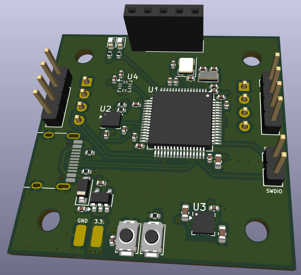
The meat and potatios, the main computer for the drone.
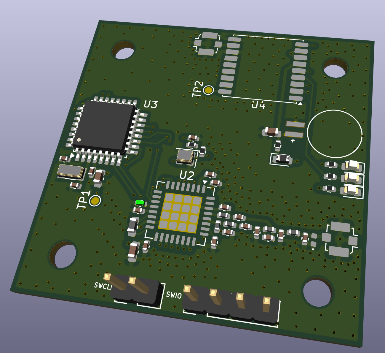
A low frequency radio to communicate with a remote controller.
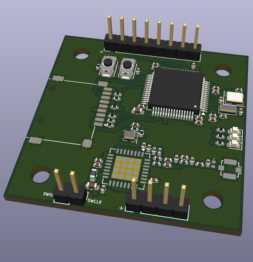
Controls the camera and captures videos and pictures with a high frequency radio for faster communication.
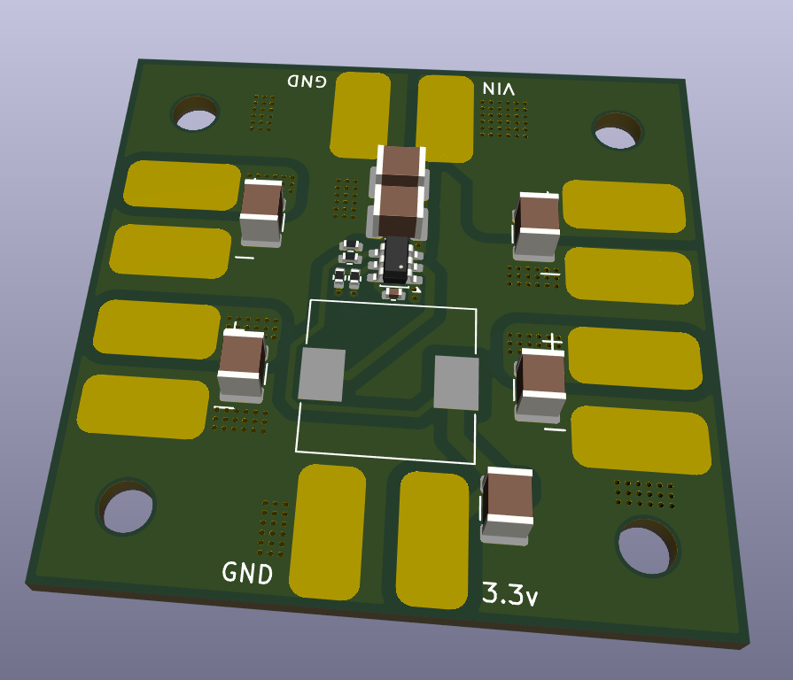
Powers the whole stack with 3.3v and connects the ESCs to the input voltage.
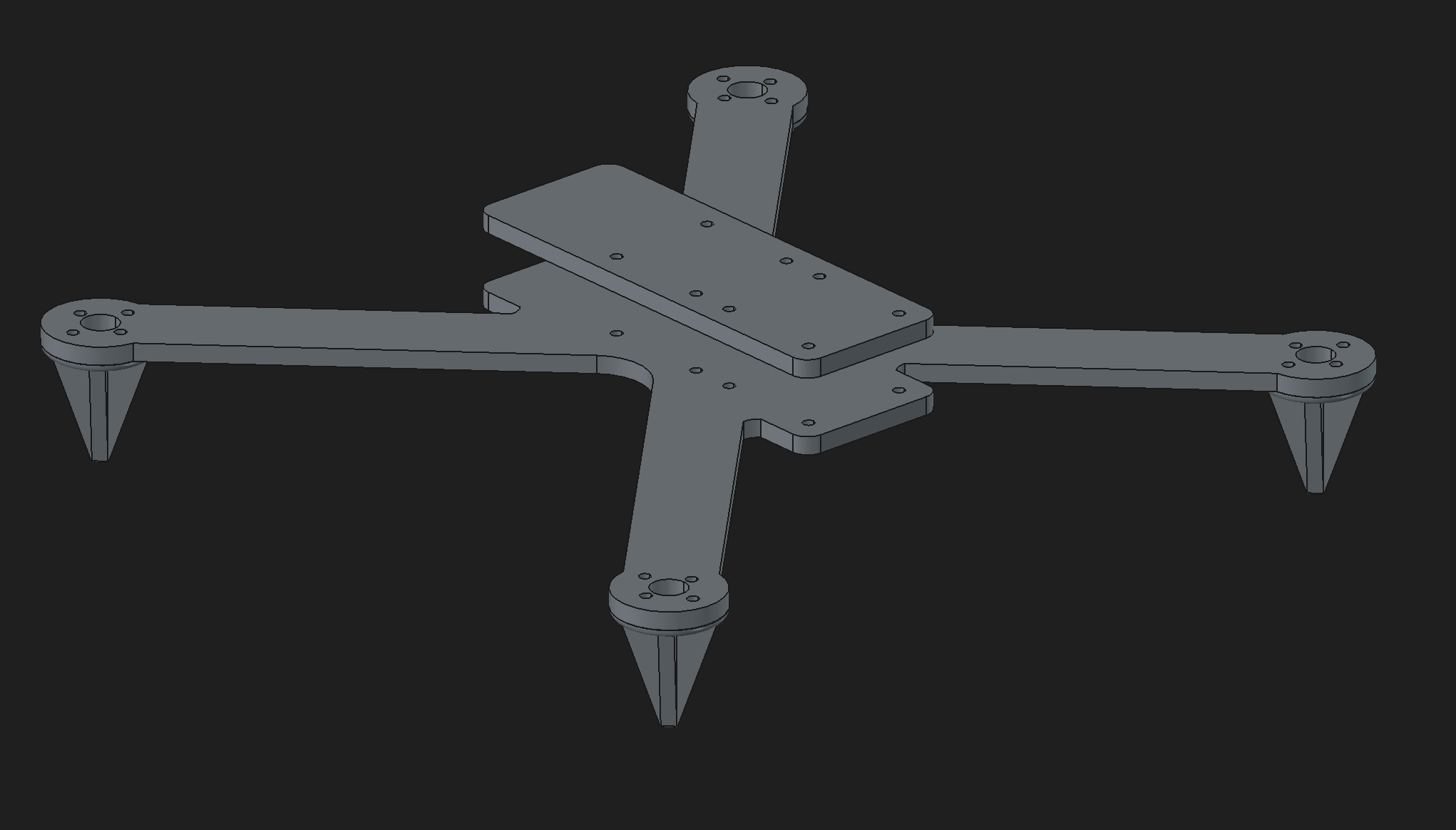
I made a custom frame to fit my custom boards and here it is.
| Name | Purpose | Quantity | Total Cost (USD) | Link | Distributor |
|---|---|---|---|---|---|
| Flight Controller Assembly | Assemble components for the flight controller | 2 | 42.44 | https://jlcpcb.com | JLCPCB |
| Flight Controller Board | The pcb for the flight controller | 5 | 2.00 | https://jlcpcb.com | JLCPCB |
| Power Board Assembly | Assemble components for the power board | 2 | 14.79 | https://jlcpcb.com | JLCPCB |
| Power Board | The pcb for the power board | 5 | 7.00 | https://jlcpcb.com | JLCPCB |
| Transceiver Assmebly | Assemble components for the board | 2 | 51.31 | https://jlcpcb.com | JLCPCB |
| Transceiver Board | The pcb for the transceiver | 5 | 7.00 | https://jlcpcb.com | JLCPCB |
| Camera Controller Assembly | Assemble components for the board | 2 | 34.63 | https://jlcpcb.com | JLCPCB |
| Camera Controller Board | The pcb for the camera controller | 5 | 7.00 | https://jlcpcb.com | JLCPCB |
| Qty | Value | Footprint | References |
|---|---|---|---|
| 3 | 1.2K | Resistor_SMD:R_0402_1005Metric | R11, R12, R13 |
| 3 | 100nF | Capacitor_SMD:C_0402_1005Metric | C18, C31, C32 |
| 3 | 47pF | Capacitor_SMD:C_0402_1005Metric | C8, C22, C23 |
| 3 | LED | LED_SMD:LED_0603_1608Metric | D4, D5, D6 |
| 2 | 1.8pF | Capacitor_SMD:C_0402_1005Metric | C11, C15 |
| 2 | 1uF | Capacitor_SMD:C_0402_1005Metric | C34, C36 |
| 2 | 2.2uF | Capacitor_SMD:C_0402_1005Metric | C35, C37 |
| 2 | 4.7uF | Capacitor_SMD:C_0603_1608Metric | C19, C33 |
| 2 | Conn_Coaxial | Connector_Coaxial:U.FL_Molex_MCRF_73412-0110_Vertical | J2, J5 |
| 2 | TestPoint | TestPoint:TestPoint_Pad_D1.0mm | TP1, TP2 |
| 1 | 120K | Resistor_SMD:R_0402_1005Metric | R4 |
| 1 | 12nH | Inductor_SMD:L_0402_1005Metric | L6 |
| 1 | 18pF | Capacitor_SMD:C_0402_1005Metric | C13 |
| 1 | 1K | Resistor_SMD:R_0402_1005Metric | R3 |
| 1 | 1nF | Capacitor_SMD:C_0402_1005Metric | C38 |
| 1 | 1uF | Capacitor_SMD:C_0603_1608Metric | C17 |
| 1 | 2.2pF | Capacitor_SMD:C_0402_1005Metric | C16 |
| 1 | 2.2uH | Inductor_SMD:L_0603_1608Metric | L1 |
| 1 | 22pF | Capacitor_SMD:C_0402_1005Metric | C9 |
| 1 | 24nH | Inductor_SMD:L_0402_1005Metric | L9 |
| 1 | 3.9nH | Inductor_SMD:L_0402_1005Metric | L10 |
| 1 | 3.9pF | Capacitor_SMD:C_0402_1005Metric | C14 |
| 1 | 32.768KHz | Crystal:Crystal_SMD_3215-2Pin_3.2x1.5mm | Y1 |
| 1 | 32MHz 10pF | Crystal:Crystal_SMD_2016-4Pin_2.0x1.6mm | Y3 |
| 1 | 4.7nH | Inductor_SMD:L_0402_1005Metric | L8 |
| 1 | 7.5nH | Inductor_SMD:L_0402_1005Metric | L11 |
| 1 | 7.5pF | Capacitor_SMD:C_0402_1005Metric | C10 |
| 1 | Conn_01x02 | Connector_PinHeader_2.54mm:PinHeader_1x02_P2.54mm_Vertical | J4 |
| 1 | Conn_01x04 | Connector_PinHeader_2.54mm:PinHeader_1x04_P2.54mm_Vertical | J3 |
| 1 | D_Schottky | Diode_SMD:D_0603_1608Metric | D3 |
| 1 | D_TVS | Diode_SMD:D_0402_1005Metric | D2 |
| 1 | ERT-J0ER104F | Resistor_SMD:R_0402_1005Metric | TH1 |
| 1 | LR2021 | Package_DFN_QFN:QFN-32-1EP_7x7mm_P0.65mm_EP4.65x4.65mm | U2 |
| 1 | MAX-M10S | RF_GPS:ublox_MAX | U4 |
| 1 | MS621FE-FL11E | imports:BAT_MS621FE-FL11E | BT1 |
| 1 | STM32G030K8Tx | Package_QFP:LQFP-32_7x7mm_P0.8mm | U3 |
The 50 most common of 54 parts.
It measures 40 × 40 mm and has 4 copper layers, 1.6 mm thick.
54 parts, built around the MAX-M10S, ERTJ0ER104FM and MS621FE-FL11E. The full list of its parts is on this page, with links to each part's symbol and footprint where PCBKit's library has them.
From the someonelse20/Shadowfax repository on GitHub, at the commit this page was made from: the board is transceiver/hardware/transceiver.kicad_pcb and its schematic ESC/hardware/ESC.kicad_sch. PCBKit opens the board in the browser, with nothing to install.
Its repository states no licence, so its author keeps all rights: ask someonelse20 before reusing the design.


antmicro/jetson-nano-baseboard
Antmicro's open hardware baseboard for the NVIDIA Jetson Nano, TX2 NX and Xavier NX

antmicro/jetson-orin-baseboard
Baseboard targetting the NVIDIA Jetson Orin Nano and Jetson Orin NX


antmicro/snapdragon-845-baseboard
https://antmicro.com/blog/2022/04/open-source-snapdragon-845-baseboard/

antmicro/jetson-agx-thor-baseboard
Open hardware baseboard for Nvidia Jetson Thor AGX T5000 System on Module

antmicro/cm4-baseboard
Experimental baseboard supporting System on Modules with Raspberry Pi CM4/CM5 pinout

CopperPilot/Jetson-AI-Cam-CopperPilot
A carrier for Jetson Nano, Xavier NX and TX2 NX with two IMX219 cameras on a 39 mm stereo baseline, dual 4K outputs and CAN.

antmicro/com-express-7-baseboard
This project contains open hardware design files for a baseboard supporting COM Express 7 modules. The board breaks-out major communications and peripheral interfaces provided by the standard.