
4 layers82 × 82 mm

 someonelse20/Shadowfax
FPV Drone designed from scrach.
Power board is an open-source printed circuit board by someonelse20, from the someonelse20/Shadowfax repository on GitHub. It is a 4-layer board of 40 × 40 mm with 30 parts on 7 nets, routed with 50 tracks and 203 vias.
It is built around the TPS54308DDC. Its parts include 12 connectors, 8 capacitors, 4 resistors, 1 IC and 1 inductor.
FPV Drone designed from scrach. This design isn't fully custom yet but will get there eventually. I started this project to make a cool drone and learn as much as I can about engineering.
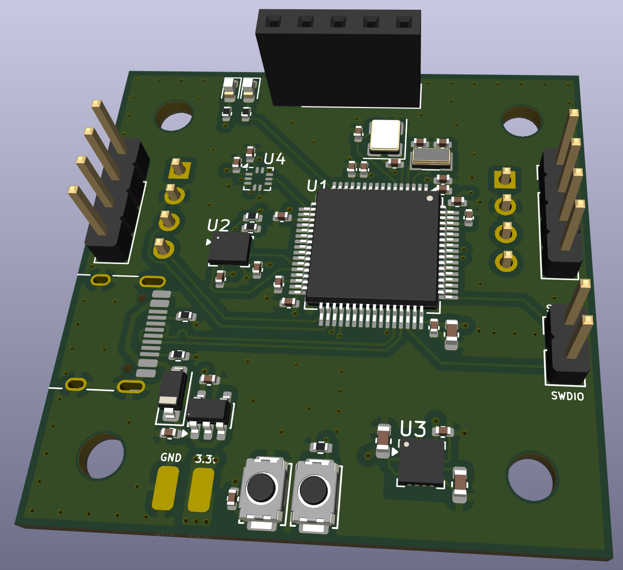
The meat and potatios, the main computer for the drone.
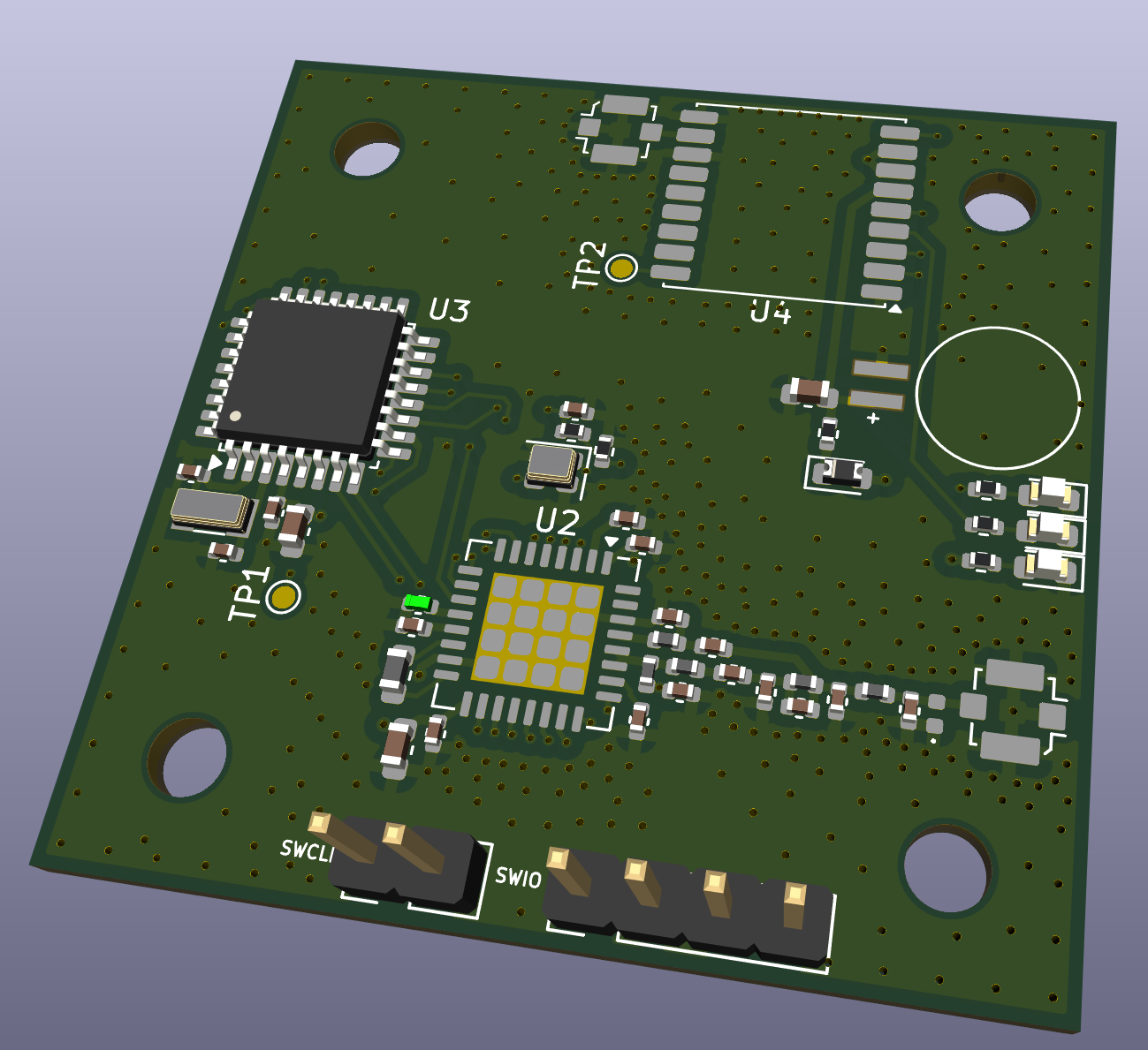
A low frequency radio to communicate with a remote controller.
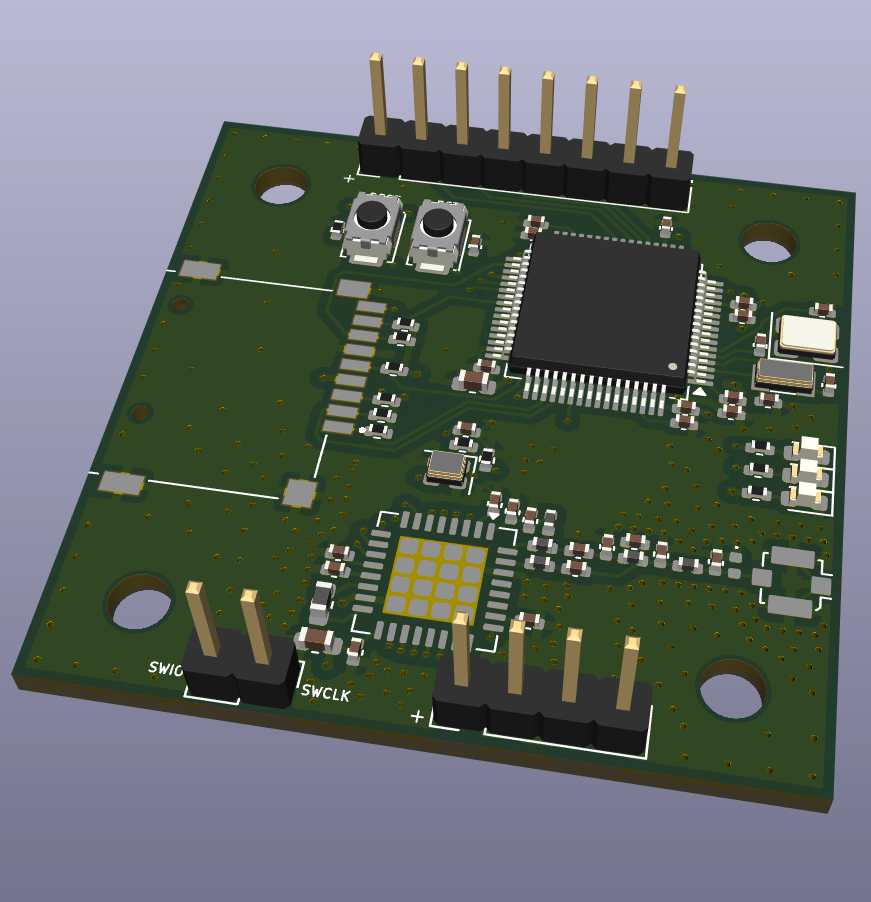
Controls the camera and captures videos and pictures with a high frequency radio for faster communication.
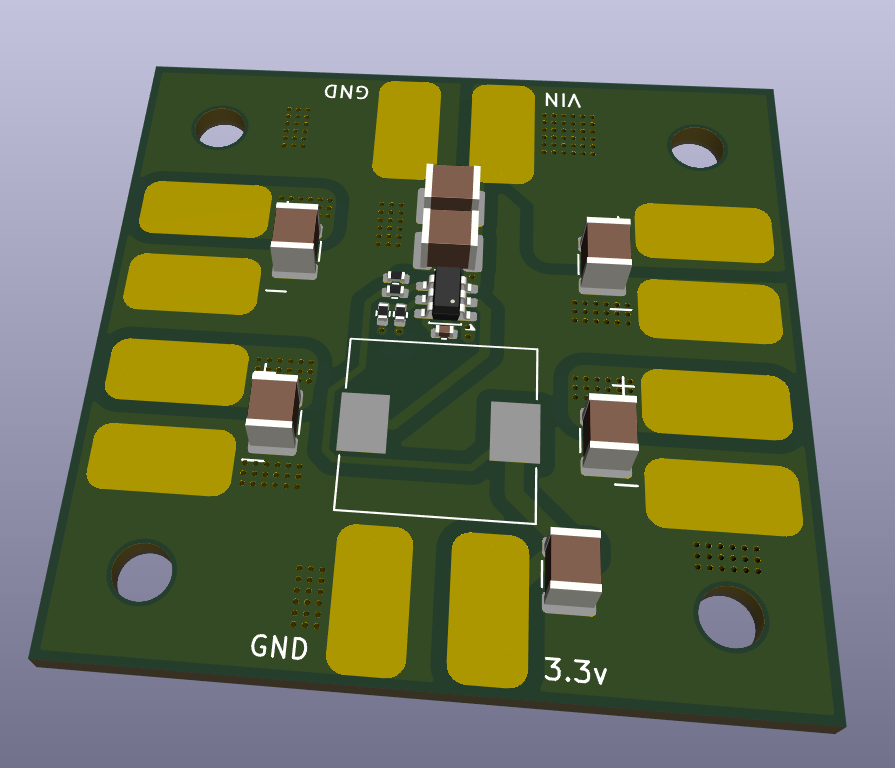
Powers the whole stack with 3.3v and connects the ESCs to the input voltage.
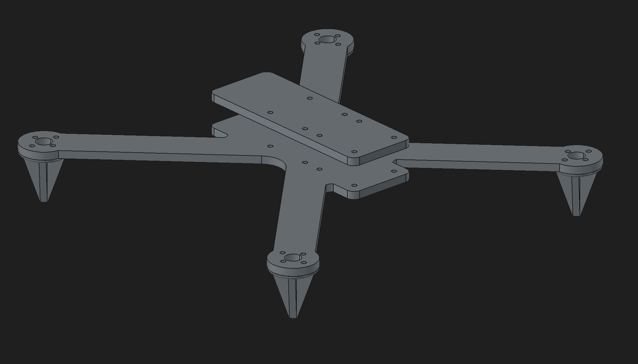
I made a custom frame to fit my custom boards and here it is.
| Name | Purpose | Quantity | Total Cost (USD) | Link | Distributor |
|---|---|---|---|---|---|
| Flight Controller Assembly | Assemble components for the flight controller | 2 | 42.44 | https://jlcpcb.com | JLCPCB |
| Flight Controller Board | The pcb for the flight controller | 5 | 2.00 | https://jlcpcb.com | JLCPCB |
| Power Board Assembly | Assemble components for the power board | 2 | 14.79 | https://jlcpcb.com | JLCPCB |
| Power Board | The pcb for the power board | 5 | 7.00 | https://jlcpcb.com | JLCPCB |
| Transceiver Assmebly | Assemble components for the board | 2 | 51.31 | https://jlcpcb.com | JLCPCB |
| Transceiver Board | The pcb for the transceiver | 5 | 7.00 | https://jlcpcb.com | JLCPCB |
| Camera Controller Assembly | Assemble components for the board | 2 | 34.63 | https://jlcpcb.com | JLCPCB |
| Camera Controller Board | The pcb for the camera controller | 5 | 7.00 | https://jlcpcb.com | JLCPCB |
| Qty | Value | Footprint | References |
|---|---|---|---|
| 12 | Conn_01x01 | Connector_Wire:SolderWirePad_1x01_SMD_4x8mm | J1, J2, J3, J4, J5, J6, J7, J8, J9, J10, J11, J12 |
| 6 | 10uF | Capacitor_SMD:C_1210_3225Metric | C1, C2, C8, C10, C12, C14 |
| 2 | 100K | Resistor_SMD:R_0402_1005Metric | R1, R3 |
| 1 | 100nF | Capacitor_SMD:C_0402_1005Metric | C4 |
| 1 | 10uH | Inductor_SMD:L_10.4x10.4_H4.8 | L1 |
| 1 | 22K | Resistor_SMD:R_0402_1005Metric | R2 |
| 1 | 33.2K | Resistor_SMD:R_0402_1005Metric | R4 |
| 1 | 47uF | Capacitor_SMD:C_1210_3225Metric | C3 |
| 1 | TPS54308 | Package_TO_SOT_SMD:SOT-23-6 | U1 |
The 26 most common of 30 parts.


hasenbanck/remram
32bit STM32F7 based 3D printing controller using TMC2130 stepper driver


felixznr/ALBERT
Albert I was a rhesus macaque monkey and the first mammal launched on a rocket (V-2 Rocket "Blossom No. 3") on June 18, 1948.

Kraad25/TPS5430_Buck_5V
12V-to-5V synchronous buck converter (TPS54308), designed in KiCad


spiwocoal/547452
Convertidor DC/DC topología SEPIC para ramo Taller de sistemas electrónicos
It measures 40 × 40 mm and has 4 copper layers, 1.6 mm thick.
30 parts, built around the TPS54308DDC. The full list of its parts is on this page, with links to each part's symbol and footprint where PCBKit's library has them.
From the someonelse20/Shadowfax repository on GitHub, at the commit this page was made from: the board is power-board/power-board.kicad_pcb and its schematic ESC/hardware/ESC.kicad_sch. PCBKit opens the board in the browser, with nothing to install.
Its repository states no licence, so its author keeps all rights: ask someonelse20 before reusing the design.