
2 layers65 × 50 mm
Mecha Dev Expander
SolidwareGit/Modular-GP2040-Dev-Board
This is a development board for the RP2040 to enable creation of a modular GP2040-CE, using I2C, for fightsticks or other controller peripherals
30 parts1CC0-1.0
 SolidwareGit/Modular-GP2040-Dev-Board1
This is a development board for the RP2040 to enable creation of a modular GP2040-CE, using I2C, for fightsticks or other controller peripherals
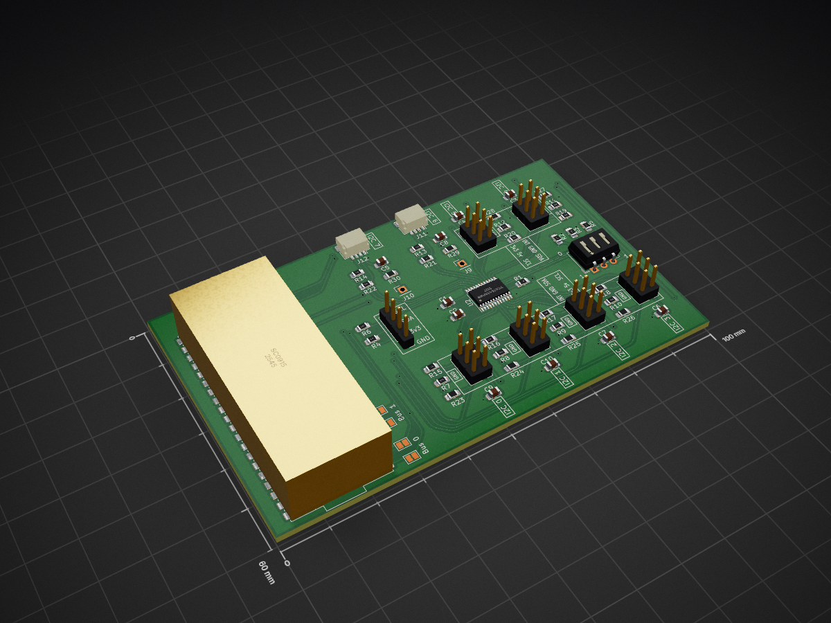
Mecha Dev Board is an open-source printed circuit board by SolidwareGit, from the SolidwareGit/Modular-GP2040-Dev-Board repository on GitHub, published under the CC0-1.0 licence. It is a 2-layer board of 100 × 60 mm with 59 parts on 57 nets, routed with 539 tracks and 70 vias.
It is built around the SC0915. Its parts include 30 resistors, 12 connectors, 10 capacitors, 2 ICs and 1 switch. It belongs with the microcontroller boards boards of this library.
This is a development board for the RP2040 to enable creation of a modular GP2040-CE, using I2C, for fightsticks or other controller peripherals
| Qty | Value | Footprint | References |
|---|---|---|---|
| 18 | 3.3k | Resistor_SMD:R_0805_2012Metric_Pad1.20x1.40mm_HandSolder | R4, R6, R7, R10, R11, R12, R13, R14, R15, R16, R17, R18, R19, R20, R21, R22 +2 |
| 9 | 1uf | Capacitor_SMD:C_0805_2012Metric_Pad1.18x1.45mm_HandSolder | C1, C3, C4, C5, C6, C7, C8, C9, C10 |
| 8 | DNF | Resistor_SMD:R_0805_2012Metric_Pad1.20x1.40mm_HandSolder | R23, R24, R25, R26, R27, R28, R29, R30 |
| 6 | Conn_02x03_Odd_Even | Connector_PinHeader_2.54mm:PinHeader_2x03_P2.54mm_Vertical | J3, J4, J5, J6, J7, J8 |
| 3 | 100k | Resistor_SMD:R_0805_2012Metric_Pad1.20x1.40mm_HandSolder | R2, R3, R5 |
| 2 | Conn_01x01_Male | Connector_PinHeader_2.54mm:PinHeader_1x01_P2.54mm_Vertical | J9, J10 |
| 2 | Conn_01x04 | Connector_JST:JST_SH_SM04B-SRSS-TB_1x04-1MP_P1.00mm_Horizontal | J11, J12 |
| 2 | Jumper Closed | Jumper:SolderJumper-2_P1.3mm_Bridged_Pad1.0x1.5mm | JP1, JP2 |
| 2 | Jumper Open | Jumper:SolderJumper-2_P1.3mm_Open_Pad1.0x1.5mm | JP3, JP4 |
| 1 | 0.1uf | Capacitor_SMD:C_0805_2012Metric_Pad1.18x1.45mm_HandSolder | C2 |
| 1 | 10K | Resistor_SMD:R_0805_2012Metric_Pad1.20x1.40mm_HandSolder | R1 |
| 1 | Conn_01x03_Male | Connector_PinHeader_2.54mm:PinHeader_1x03_P2.54mm_Vertical | J2 |
| 1 | Conn_01x04_Male | Connector_PinHeader_2.54mm:PinHeader_1x04_P2.54mm_Vertical | J1 |
| 1 | SC0915 | footprints:SC0915 | U1 |
| 1 | SW_DIP_x03 | Button_Switch_THT:SW_DIP_SPSTx03_Slide_6.7x9.18mm_W7.62mm_P2.54mm_LowProfile | SW1 |
| 1 | TCA9548APWR | Package_SO:TSSOP-24_4.4x7.8mm_P0.65mm | U2 |
It measures 100 × 60 mm and has 2 copper layers, 1.6 mm thick.
59 parts, built around the SC0915. The full list of its parts is on this page, with links to each part's symbol and footprint where PCBKit's library has them.
From the SolidwareGit/Modular-GP2040-Dev-Board repository on GitHub, at the commit this page was made from: the board is Mecha Dev Board/Mecha Dev Board.kicad_pcb and its schematic Mecha Dev Board/Mecha Dev Board.kicad_sch. PCBKit opens the board in the browser, with nothing to install.
Its repository publishes it under the CC0-1.0 licence: you may reuse it on that licence's terms (keep the author's notice, and for a copyleft licence share your changes alike).
SolidwareGit/Modular-GP2040-Dev-Board
This is a development board for the RP2040 to enable creation of a modular GP2040-CE, using I2C, for fightsticks or other controller peripherals

Rack-Robotics/Powercore-V3
electrical-discharge power supply, open-source


jackw01/pi-pico-printer-board
Tinkerer-friendly Klipper compatible 3D printer control board using Raspberry Pi Pico


Supermagnum/Europe-ergo
A 94 key ergonomic, split keyboard suitable for European countries.

lambdaBoost/MC6205-graphical-display
graphical display on old neon plasma screen

