2 layers154 × 123 mm
 lambdaBoost/MC6205-graphical-display7
graphical display on old neon plasma screen
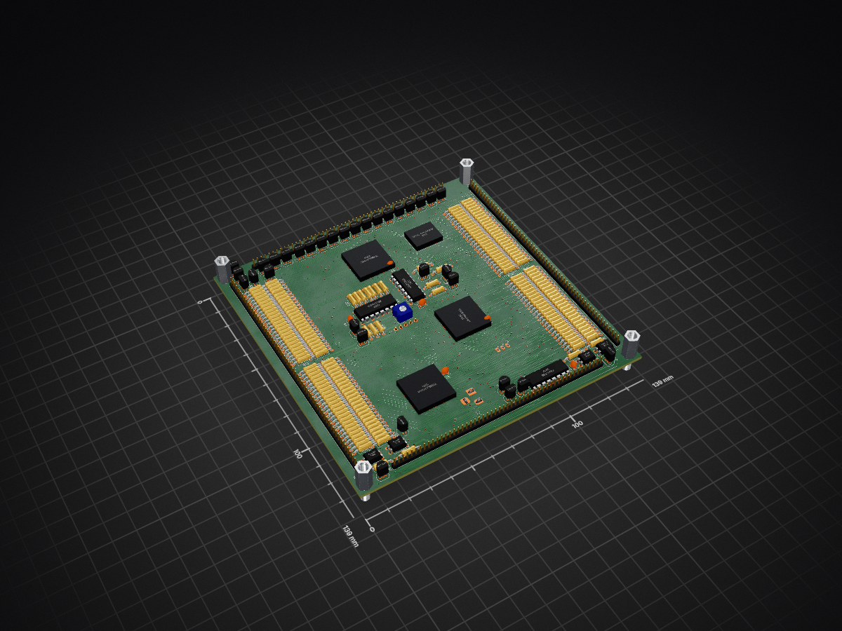
Screen driver is an open-source printed circuit board by lambdaBoost, from the lambdaBoost/MC6205-graphical-display repository on GitHub. It is a 2-layer board of 139 × 139 mm with 285 parts on 426 nets, routed with 3,603 tracks and 497 vias.
It is built around the SC0915, TSR 1-2450 and TLP627(F), with the CD4017BE, 74HC595 and MPSA42 among its other parts. Its parts include 218 resistors, 33 transistors, 13 ICs, 10 connectors and 6 capacitors. It belongs with the lEDs and displays boards of this library.


graphical display on old neon plasma screen.

This is a two part project using the Soviet Ukrainian MC6205 plasma display. Part 1 uses the unaltered device with an ESP32 in order to display text info from any suitable webpage or API. Part 2 will convert the device into a full graphical display (ie not just text).
The device itself is a monochrome neon plasma display, produced throughout the 1980s and early 1990s in Soviet Ukraine. It is capable of displaying text on a 100x100px screen. This is achieved by supplying appropriate serial inputs to the 64 pin connector on the base of the display. Included in the package is an EEPROM which converts the serial inputs into text characters. This unfortunately mean the MC6205 is only capable of displaying text, but part 2 will see me re-wiring and adding a custom PCB to allow for full graphical display.
To demo part 1, I'm using the device to provide live updates on Russian vehicle losses. Data is from the excellent Oryx loss tracker
Fortunately someone else did the hard work and wrote an arduino library arduino library to display text to the display, so all I needed to do was hook it up to the ESP32 (following the instructions from the linked repo).
Data is provided by a custom API which runs on a seperate machine. In my case, the API runs from a raspberry pi and is queried by the ESP32. This avoided having to attempt to parse the webpage in Arduino...which would be a nightmare. The code for part 2 will be in Micropython which I find much easier to work with.
For now, the setup is wired up via a breadboard. When part 2 is complete it will be entirely contained in the original enclosure.

To build the vehicle tracker display in the exact format shown here you will need:
To build the vehicle loss tracker do the following:
docker-compose up -difconfig)| Qty | Value | Footprint | References |
|---|---|---|---|
| 100 | 330k | Resistor_THT:R_Axial_DIN0207_L6.3mm_D2.5mm_P10.16mm_Horizontal | R100, R102, R103, R104, R105, R106, R107, R108, R109, R110, R111, R119, R120, R121, R122, R123 +84 |
| 100 | 390k | Resistor_THT:R_Axial_DIN0207_L6.3mm_D2.5mm_P10.16mm_Horizontal | R1, R10, R11, R12, R13, R14, R15, R16, R17, R169, R170, R171, R172, R173, R174, R175 +84 |
| 32 | MPSA42 | Package_TO_SOT_THT:TO-92_Inline | Q1, Q2, Q10, Q11, Q12, Q13, Q14, Q15, Q16, Q17, Q18, Q19, Q20, Q21, Q22, Q23 +16 |
| 12 | R | Resistor_THT:R_Axial_DIN0207_L6.3mm_D2.5mm_P7.62mm_Horizontal | R51, R52, R53, R54, R55, R56, R57, R58, R59, R60, R101, R112 |
| 6 | C_Small | Capacitor_THT:C_Disc_D3.8mm_W2.6mm_P2.50mm | C1, C2, C3, C4, C5, C6 |
| 4 | 330 | Resistor_THT:R_Axial_DIN0207_L6.3mm_D2.5mm_P10.16mm_Horizontal | R113, R114, R115, R116 |
| 4 | TLP627 | Package_DIP:DIP-4_W7.62mm | U2, U3, U12, U13 |
| 3 | , , | ||
| 3 | YH5504KH01 | soviet:YH5504KH01 | U7, U8, U11 |
| 2 | CD4017BE | Package_DIP:DIP-16_W7.62mm | U5, U6 |
| 1 | 100 | Resistor_THT:R_Axial_DIN0207_L6.3mm_D2.5mm_P10.16mm_Horizontal | R118 |
| 1 | 10k | Resistor_THT:R_Axial_DIN0207_L6.3mm_D2.5mm_P10.16mm_Horizontal | R117 |
| 1 | 74HC595 | Package_DIP:DIP-16_W7.62mm | U9 |
| 1 | ANODE - EVEN 2-60 | Connector_PinHeader_2.00mm:PinHeader_1x40_P2.00mm_Vertical | J2 |
| 1 | ANODE - EVEN-62-100 | Connector_PinHeader_2.00mm:PinHeader_1x20_P2.00mm_Vertical | J3 |
| 1 | ANODE - ODD 1-59 | Connector_PinHeader_2.00mm:PinHeader_1x40_P2.00mm_Vertical | J8 |
| 1 | ANODE - ODD 61-99 | Connector_PinHeader_2.00mm:PinHeader_1x20_P2.00mm_Vertical | J9 |
| 1 | BC547 | Package_TO_SOT_THT:TO-92_Inline | Q33 |
| 1 | Barrel_Jack_Switch | Connector_BarrelJack:BarrelJack_Horizontal | J1 |
| 1 | CATHODE - EVEN - 42-100 | Connector_PinHeader_2.00mm:PinHeader_1x40_P2.00mm_Vertical | J4 |
| 1 | CATHODE EVEN 2-40 | Connector_PinHeader_2.00mm:PinHeader_1x12_P2.00mm_Vertical | J6 |
| 1 | CATHODE ODD 1-39 | Connector_PinHeader_2.00mm:PinHeader_1x12_P2.00mm_Vertical | J7 |
| 1 | CATHODE ODD 41-99 | Connector_PinHeader_2.00mm:PinHeader_1x40_P2.00mm_Vertical | J5 |
| 1 | Conn_01x05_Male | Connector_PinHeader_2.54mm:PinHeader_1x05_P2.54mm_Vertical | J10 |
| 1 | R_Potentiometer | Potentiometer_THT:Potentiometer_Vishay_T73YP_Vertical | RV1 |
| 1 | SC0915 | SC0915:MODULE_SC0915 | U1 |
| 1 | TSR_1-2450 | Converter_DCDC:Converter_DCDC_TRACO_TSR-1_THT | U4 |
| 1 | level_converter | daughter_boards:level_shifter | U10 |
The 284 most common of 285 parts.

snakeye/nixie-clock
Nixie clock based on ESP32-C3 Super Mini module and Soviet IN-14 tubes


bitsoko-services/narra
This repository contains hardware designs and software for Narra, an open source, BLE advertising and control, LED signage platform. The project utilises the ESP32 and the ESP-IDF framework.

Majklzbastlirny/NixieClock
ESP-IDF firmware for a 6-tube multiplexed ESP32 nixie clock (WiFi/SNTP, Home Assistant, web UI, alarm, temperatures)

profdc9/NixieClock
A Nixie clock that uses IN-14 tubes and very generic components that can be easily sourced.


It measures 139 × 139 mm and has 2 copper layers, 1.6 mm thick.
285 parts, built around the SC0915, TSR 1-2450, TLP627(F) and CD4017BE. The full list of its parts is on this page, with links to each part's symbol and footprint where PCBKit's library has them.
From the lambdaBoost/MC6205-graphical-display repository on GitHub, at the commit this page was made from: the board is full-graphical/PCB/screen-driver/screen-driver.kicad_pcb and its schematic full-graphical/PCB/screen-driver/screen-driver.kicad_sch. PCBKit opens the board in the browser, with nothing to install.
Its repository states no licence, so its author keeps all rights: ask lambdaBoost before reusing the design.