


2 layers101.5 × 83 mm

 sneakylizard123-4/CS4344
The CS4344 is a 24-bit stereo DAC that accepts I2S audio and runs from a single 3.3 V supply. This board gives it a 6-pin 2.54 mm header, a 3.5 mm stereo jack, and the passives it needs. There is no configuration bus.
CS4344 is an open-source printed circuit board by sneakylizard123-4, from the sneakylizard123-4/CS4344 repository on GitHub, published under the CERN-OHL-P-2.0 licence. It is a 2-layer board of 18.5 × 25 mm with 14 parts on 14 nets, routed with 88 tracks and 23 vias.
It is built around the CS4344. Its parts include 7 capacitors, 4 resistors, 2 connectors and 1 IC.
A compact 24-bit / 192 kHz stereo DAC for I2S audio projects.
SPDX-License-Identifier: CERN-OHL-P-2.0
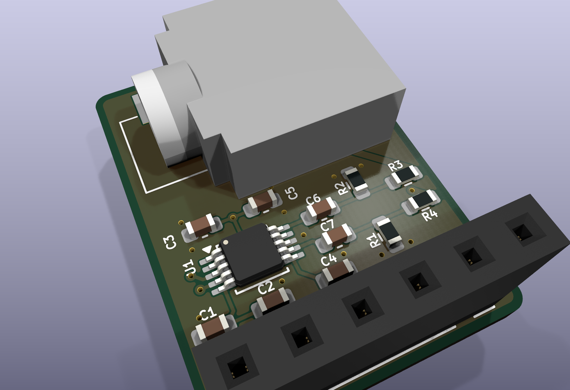
The CS4344 is a 24-bit stereo DAC that accepts I2S audio and runs from a single 3.3 V supply. This board gives it a 6-pin 2.54 mm header, a 3.5 mm stereo jack, and the passives it needs. There is no configuration bus. The DAC is in hardware mode, so the host only has to provide clocks and data.
The PCB is 18.5 x 25.0 mm, two layers. The repository also includes a STEP assembly, a parametric 3D-printable case, and an ESP32-S3 test firmware example.
I wanted a small, reusable I2S output board for FPGA and microcontroller projects. The CS4344 is inexpensive, supports 24-bit / 192 kHz audio, and has a simple hardware interface. The board has a real jack so it can be used outside a breadboard.
The signal path is short: I2S comes in on J2, the CS4344 converts it, and the output network drives the jack.
| Block | Main parts | Function |
|---|---|---|
| I2S input | J2 | 3.3 V, ground, SD, SCK, FS, and MCLK |
| DAC | U1 | CS4344 stereo I2S DAC |
| Analog output | C6, C7, R1-R4, J1 | AC coupling, series resistance, and 3.5 mm output |
| Supply and reference decoupling | C1-C5 | VA, VQ, and FILT+ decoupling |
J2.1  +3.3V ---+--- U1.9  VA
               |
               +--- C3 1 uF --- GND
               |
               +--- C5 100 nF --- GND

U1.5  VQ ------+--- C1 10 uF --- GND
               |
               +--- C2 100 nF --- GND

U1.6  FILT+ ---+--- C4 10 uF --- GND
The CS4344 is a 3.3 V part. Do not power the board from 5 V. VQ and FILT+ are internal reference/filter nodes; they are decoupled on the board and must not be driven from outside.
J2.2  SD   -> U1.1  SDIN
J2.3  SCK  -> U1.2  SCLK
J2.4  FS   -> U1.3  LRCK
J2.5  MCLK -> U1.4  MCLK
The host must supply MCLK. There is no oscillator on the board. The CS4344 accepts several MCLK-to-FS ratios in hardware mode; check the datasheet for the ratio your host uses.
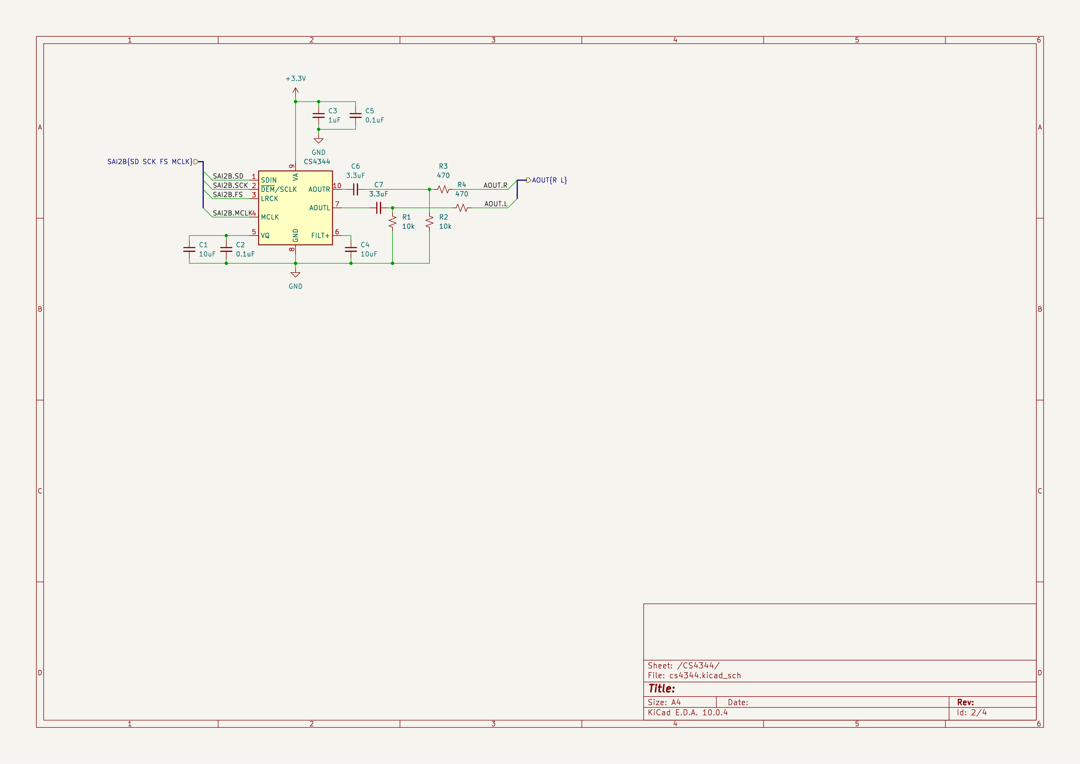
U1.7  AOUTL -> C7 3.3 uF -> node L -> R4 470 ohm -> J1 tip
                              |
                              +-> R1 10 k -> GND

U1.10 AOUTR -> C6 3.3 uF -> node R -> R3 470 ohm -> J1 ring
                              |
                              +-> R2 10 k -> GND

J1 sleeve -> GND
Each output is AC-coupled so the DAC's DC bias does not appear at the jack. The 10 k resistor keeps the coupling capacitor's output node referenced to ground, and the 470 ohm resistor limits current into the cable. This is a line-level output, not a headphone amplifier. Use an external headphone amp or powered speakers if you need more drive.
The design is split into four KiCad sheets:
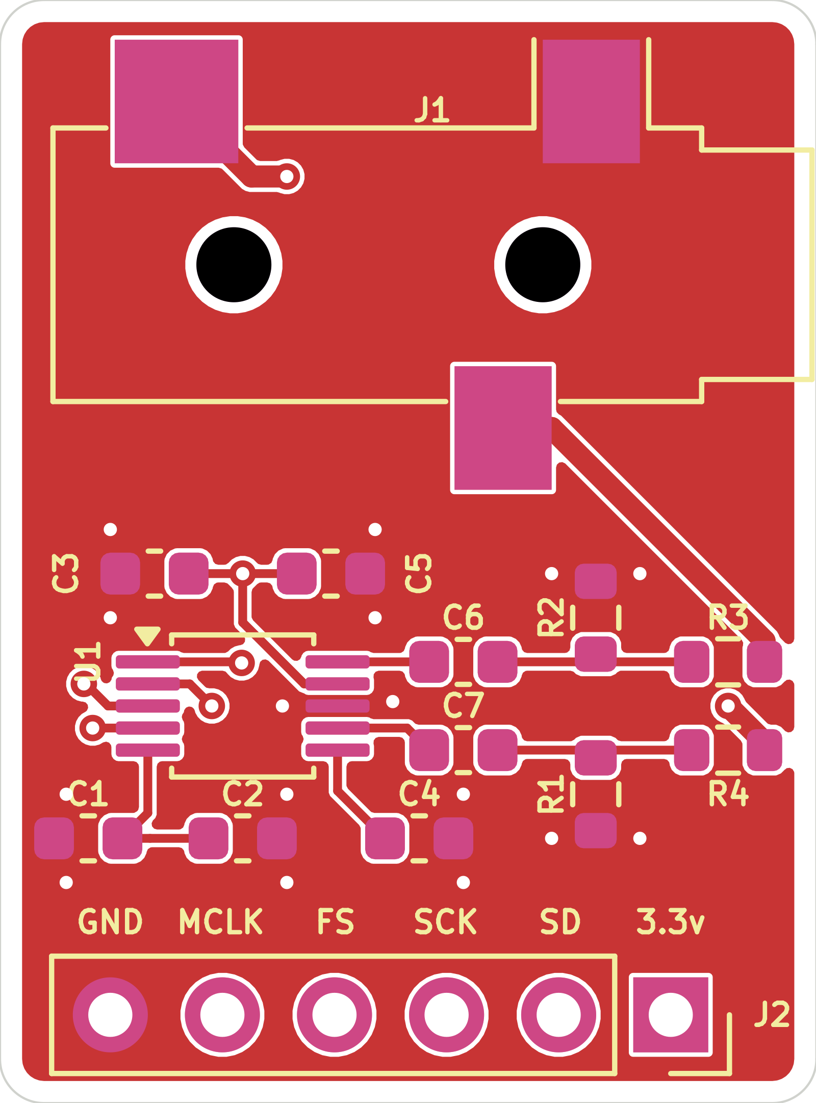
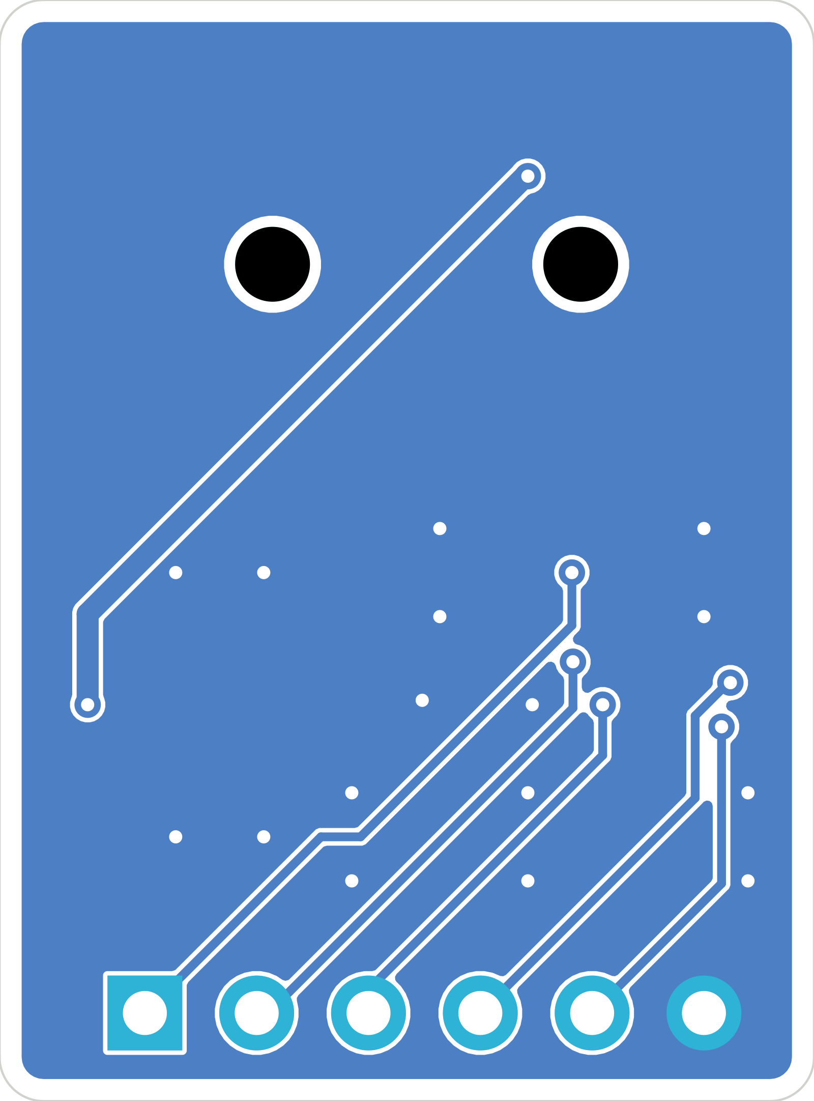
| Top | Bottom |
|---|---|
 |  |
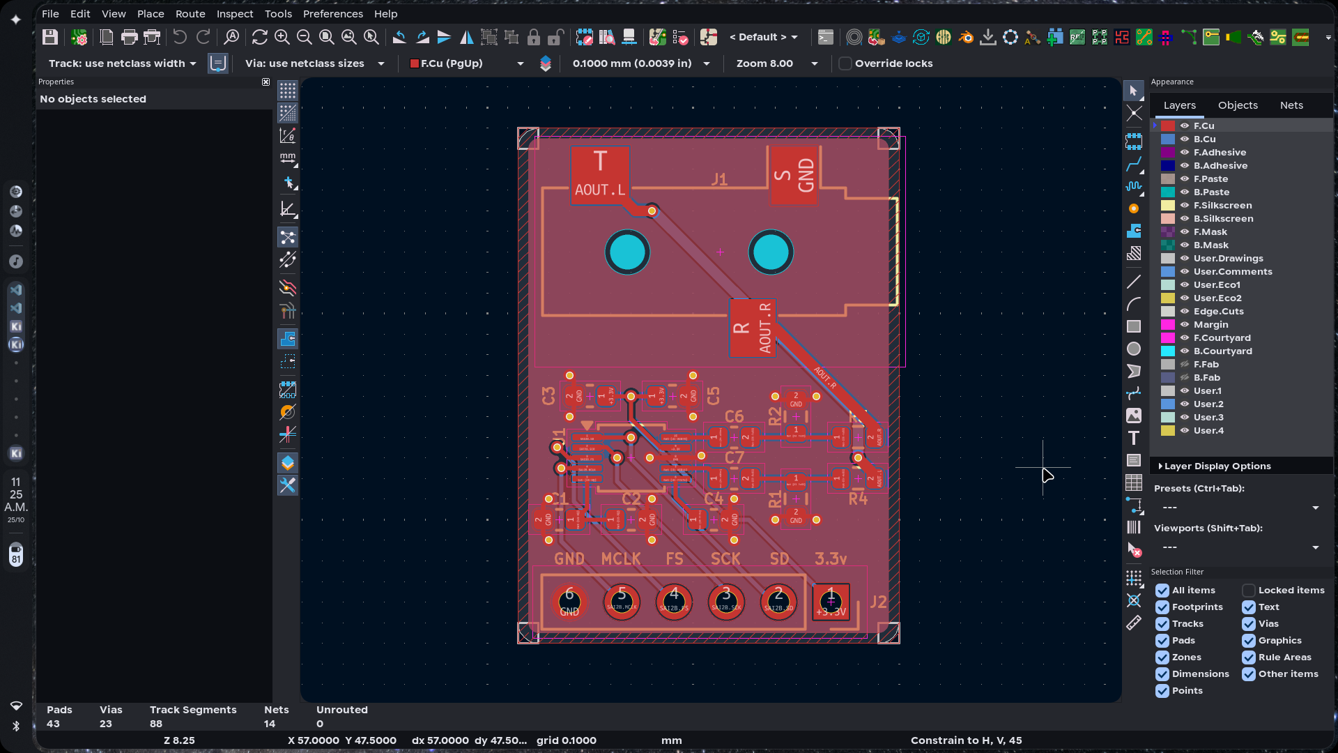
More views:
The case is a two-part print: a base with screw posts and board ledges, and a lid with a header slot, registration lips, and a hold-down rib. The jack opening is on the right-hand wall. The lid is fixed with four M2 self-tapping screws. The outside size is 30 x 36 mm, 19.4 mm tall with the lid fitted and 20.8 mm including the screw heads.
| Assembled | Cutaway | Exploded |
|---|---|---|
 |  | 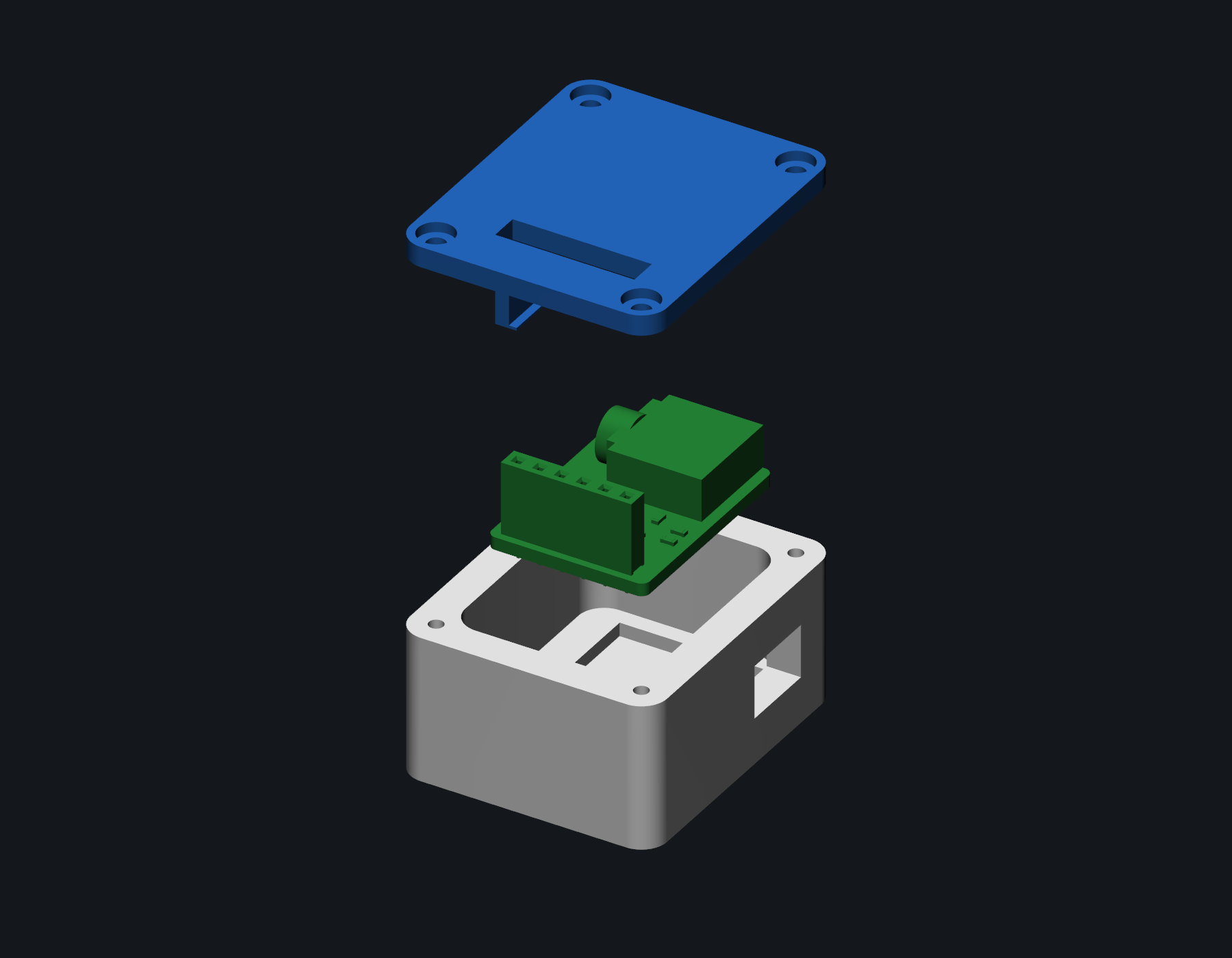 |
The enclosure is parametric CadQuery. Edit the constants at the top of cad/enclosure.py and rerun the script to regenerate the STEP and STL files. The full board and case assembly is in cad/CS4344-full-assembly.step, and the board and electronics assembly is in cad/CS4344-assembly.step. It has not been printed or test-fitted yet.
Suggested print settings:
Use 3.3 V logic levels. The board does not include level shifters.
| J2 pin | Signal | Direction | Notes |
|---|---|---|---|
| 1 | +3.3V | Power in | 3.3 V only |
| 2 | SD | Input | I2S serial data |
| 3 | SCK | Input | I2S bit clock |
| 4 | FS | Input | I2S frame clock / LRCK |
| 5 | MCLK | Input | Master clock, required |
| 6 | GND | Power | Ground |
| J1 contact | Signal |
|---|---|
| Tip | Left channel |
| Ring | Right channel |
| Sleeve | Ground |
There is no firmware on the board. The host does all of the I2S setup. An ESP32-S3 test example is in firmware/.
The board has no MCU, so the firmware in firmware/ runs on a host board. The example targets an ESP32-S3-DevKitC-1 and outputs a 1 kHz stereo sine at 48 kHz. It is meant as a bring-up test for the DAC and the analog output path.
SPDX-License-Identifier: MIT
| Signal | CS4344 J2 pin | ESP32-S3 pin |
|---|---|---|
| +3.3 V | 1 | 3V3 |
| SD | 2 | GPIO6 |
| SCK | 3 | GPIO4 |
| FS | 4 | GPIO5 |
| MCLK | 5 | GPIO7 |
| GND | 6 | GND |
The example runs I2S in standard mode with MCLK at 12.288 MHz, BCLK at 3.072 MHz, and LRCK at 48 kHz. It writes 24-bit samples left-aligned in 32-bit slots. The 32-bit slot keeps the 64 x Fs bit clock that the CS4344 expects. See firmware/README.md for the build, flash, and test steps.
cd firmware
pio run
pio run -t upload
pio device monitor
The example compiles but has not been run on a fabricated board yet.
Prices are in USD and cover one set of electronics, the five-board JLCPCB minimum, and a 10-pack of M2 screws. Shipping, tax, and assembly fees are not included. The root BOM.csv has a purchase link on every part line.
| Ref | Qty | Part | Package | Supplier | Part number | Unit price |
|---|---|---|---|---|---|---|
| U1 | 1 | CS4344-CZZR | TSSOP-10 | LCSC | C8952 | $1.5154 |
| J1 | 1 | SJ-3523-SMT-TR | SMD jack | Digi-Key | CP-3523SJCT-ND | $0.8800 |
| J2 | 1 | 1x6 2.54 mm female header | THT | LCSC | C40877 | $0.0889 |
| C1, C4 | 2 | 10 uF 10 V X5R | 0603 | LCSC | C19702 | $0.0272 |
| C2, C5 | 2 | 100 nF 50 V X7R | 0603 | LCSC | C14663 | $0.0084 |
| C3 | 1 | 1 uF 50 V X5R | 0603 | LCSC | C15849 | $0.0146 |
| C6, C7 | 2 | 3.3 uF 10 V X5R | 0603 | LCSC | C51412 | $0.0601 |
| R1, R2 | 2 | 10 k 1% | 0603 | LCSC | C25804 | $0.0022 |
| R3, R4 | 2 | 470 ohm 1% | 0603 | LCSC | C23179 | $0.0023 |
| PCB | 5 | CS4344 PCB | 18.5 x 25 mm | JLCPCB | - | $0.4000 |
| HW1 | 1 | M2 x 8 mm self-tapping screw, 10-pack | M2 | Motion RC | BCT5040-022 | $1.0900 |
| Electronics subtotal | $2.6993 |
| 5 PCBs | $2.0000 |
| Screws, 10-pack | $1.0900 |
| Total, excluding shipping and tax | $5.7893 |
That total buys one set of electronics, five bare PCBs, and a 10-pack of screws. You can build one board, keep four spare PCBs, and use 4 of the 10 screws.
The exact CUI jack is out of stock at LCSC. The Digi-Key part is the same SJ-3523-SMT-TR and was in stock when I checked.
Fabrication files are in kicad/production/:
CS4344.zip - Gerbers and drill files.bom.csv - assembly BOM.positions.csv - pick-and-place positions.designators.csv - designator list.netlist.ipc - IPC netlist.The board has not been ordered yet. The enclosure has not been printed yet.
CS4344/
|-- README.md
|-- JOURNAL.md
|-- BOM.csv
|-- LICENSE
|-- LICENSE-MIT
|-- .gitignore
|-- kicad/
|   |-- CS4344.kicad_pro
|   |-- CS4344.kicad_sch
|   |-- connector.kicad_sch
|   |-- cs4344.kicad_sch
|   |-- jack.kicad_sch
|   |-- CS4344.kicad_pcb
|   |-- sym-lib-table
|   |-- fabrication-toolkit-options.json
|   `-- production/
|       |-- CS4344.zip
|       |-- bom.csv
|       |-- designators.csv
|       |-- netlist.ipc
|       `-- positions.csv
|-- cad/
| |-- enclosure.pyHardware design files and documentation are licensed under the CERN Open Hardware Licence Version 2 - Permissive (CERN-OHL-P-2.0). See LICENSE.
SPDX-License-Identifier: CERN-OHL-P-2.0
The example firmware in firmware/ is licensed under the MIT License. See LICENSE-MIT.
SPDX-License-Identifier: MIT
| Qty | Value | Footprint | References |
|---|---|---|---|
| 2 | 0.1uF | Capacitor_SMD:C_0603_1608Metric | C2, C5 |
| 2 | 10k | Resistor_SMD:R_0603_1608Metric | R1, R2 |
| 2 | 10uF | Capacitor_SMD:C_0603_1608Metric | C1, C4 |
| 2 | 3.3uF | Capacitor_SMD:C_0603_1608Metric | C6, C7 |
| 2 | 470 | Resistor_SMD:R_0603_1608Metric | R3, R4 |
| 1 | 1uF | Capacitor_SMD:C_0603_1608Metric | C3 |
| 1 | AudioJack3 | Connector_Audio:Jack_3.5mm_CUI_SJ-3523-SMT_Horizontal | J1 |
| 1 | CS4344 | Package_SO:TSSOP-10_3x3mm_P0.5mm | U1 |
| 1 | Conn_01x06 | Connector_PinSocket_2.54mm:PinSocket_1x06_P2.54mm_Vertical | J2 |


amundgr/proto_pico
A mash of several different projects in one PCB in an attempt to kicak start all of them at once. Why fail and give up on one project when you can do it on several at once!


ppisljar/freeesp32_audioplayer
ESP32 Audio Player main board (KiCad, XIAO ESP32-S3)

sneakylizard123-4/STM32H743
This board puts an STM32H743XIH6 and an iCE40 UP5K on the same PCB. The H743 handles control, USB, Ethernet, storage, and audio.
It measures 18.5 × 25 mm and has 2 copper layers, 1.6 mm thick.
14 parts, built around the CS4344. The full list of its parts is on this page, with links to each part's symbol and footprint where PCBKit's library has them.
From the sneakylizard123-4/CS4344 repository on GitHub, at the commit this page was made from: the board is kicad/CS4344.kicad_pcb and its schematic kicad/CS4344.kicad_sch. PCBKit opens the board in the browser, with nothing to install.
Its repository publishes it under the CERN-OHL-P-2.0 licence: you may reuse it on that licence's terms (keep the author's notice, and for a copyleft licence share your changes alike).