4 layers100 × 100 mm
Pdb
javierveras/projectav-telemetry-pdb-2026
Our power distribution and telemetry system's hardware, firmware, and technical documentation.
104 parts

 snalvc/ESwitch2
A high-side N-MOSFET electrical switch module
ESwitch is an open-source printed circuit board by snalvc, from the snalvc/ESwitch repository on GitHub, published under the MIT licence. It is a 2-layer board of 45 × 45 mm with 23 parts on 13 nets, routed with 100 tracks and 28 vias.
It is built around the LM5060MM, MSK12C02 and XT90PW-F, with the XT90PW-M.G.Y among its other parts. Its parts include 6 resistors, 4 connectors, 2 capacitors, 1 IC and 1 transistor.


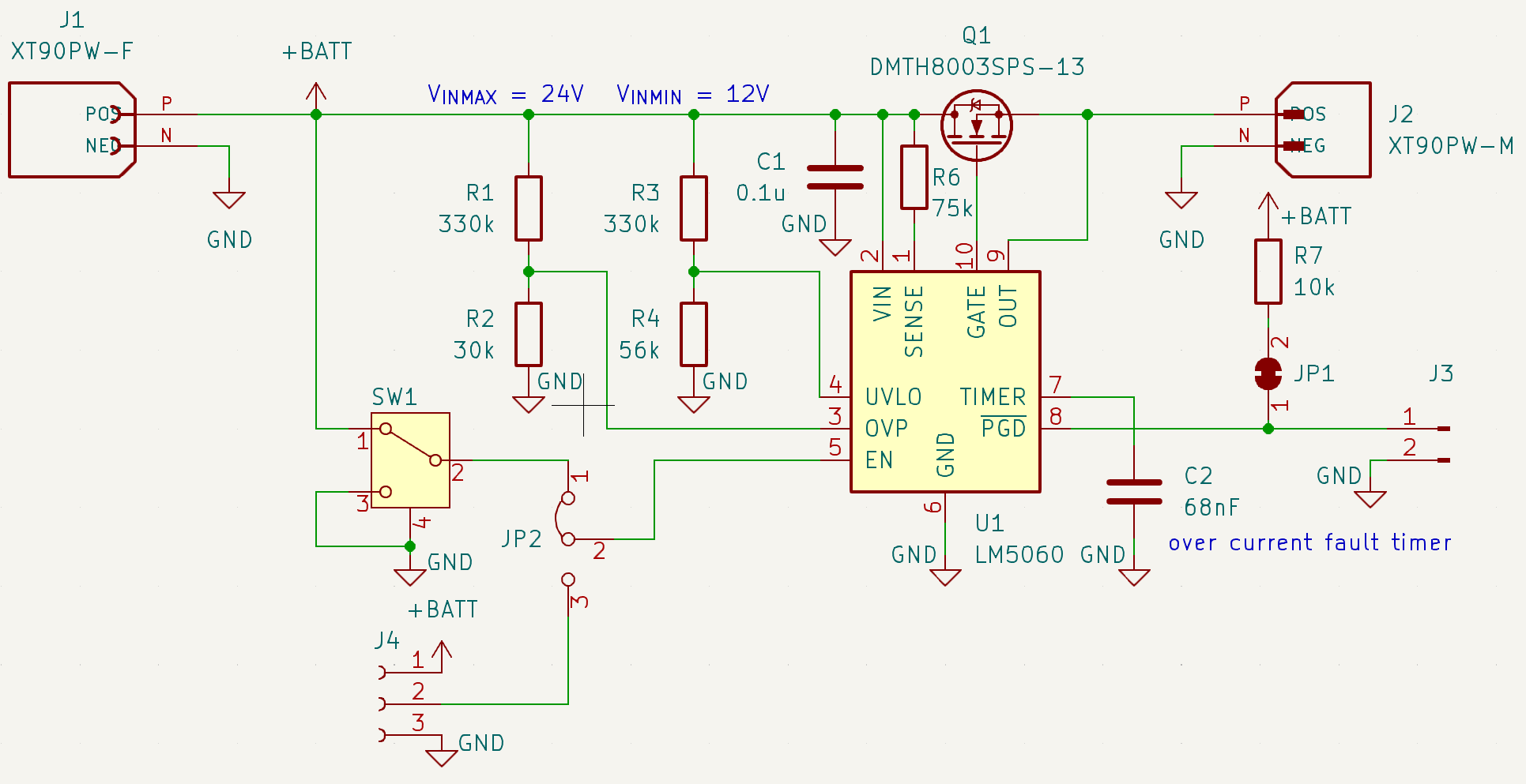
This is a high-side N-channel MOSFET electrical switch module. The power MOSFET (DMTH8003SPS) is driven by a high-side protection controller (LM5060). The schematics and PCB layout are designed in KiCad and available in the kicad directory. All the components are available in LCSC at least at the time of writing. It is also designed for single-sided PCBA with a few exceptions in the high current traces because you'll want them to be reinforced. Plus, I doubt XT90 can be assembled by cheap PCBAs anyway. There are also some Python utilities which are helpful for you to determine the required component values for various protections provided by the LM5060. In short:
utils.kicad.assemble. You can also find the BOM there.I should have positioned the high-current traces on the bottom layer, allowing for reinforcement by adding solder or copper plates onto them.
Fortunately, by chance, I made a mistake with the XT90 socket and plug. Consequently, I can easily swap the socket and plug, relocating them to the back side of the board, thereby preventing any interference with the high-current traces.
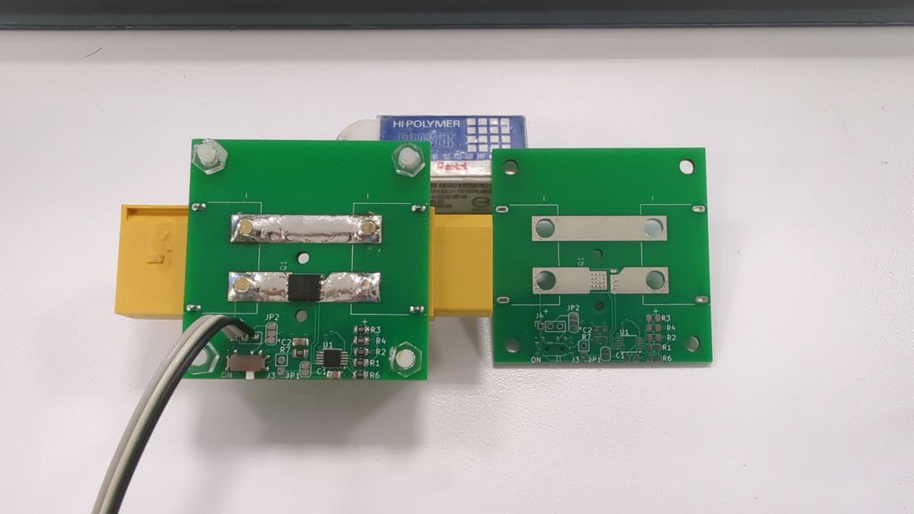
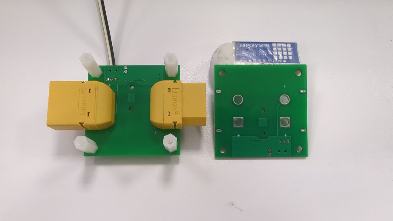
Not the prettiest welding nor photography, but it works. You get the idea of the bugs that canceled each other out. The XT90s were meant to be on the top side, but the polarity (socket and plug) was wrong. In order to get the polarity (socket, plug) right, the XT90s need to be positioned on the bottom side when swapped, which luckily achieved the desired outcome (leaving top traces for reinforcement).
2024-03-13: I have a module that has become consistently conductive. Electrostatic discharge (ESD) is suspected as the cause, especially considering it was originally functioning properly.
| Qty | Value | Footprint | References |
|---|---|---|---|
| 4 | R | Resistor_SMD:R_0805_2012Metric | R1, R2, R3, R4 |
| 1 | 0.1u | Capacitor_SMD:C_0805_2012Metric | C1 |
| 1 | 10k | Resistor_SMD:R_0805_2012Metric | R7 |
| 1 | 68nF | Capacitor_SMD:C_0805_2012Metric | C2 |
| 1 | 75k | Resistor_SMD:R_0805_2012Metric | R6 |
| 1 | Conn_01x02_Pin | Connector_PinHeader_2.00mm:PinHeader_1x02_P2.00mm_Vertical | J3 |
| 1 | Conn_01x03_Socket | Connector_PinSocket_2.00mm:PinSocket_1x03_P2.00mm_Vertical | J4 |
| 1 | DMTH8003SPS-13 | Components:PowerDI5060-8 (Type K) | Q1 |
| 1 | Jumper_3_Bridged12 | Jumper:SolderJumper-3_P1.3mm_Bridged12_RoundedPad1.0x1.5mm | JP2 |
| 1 | LM5060 | Package_SO:MSOP-10_3x3mm_P0.5mm | U1 |
| 1 | MSK12C02 | LIB_MSK12C02:MSK12C02 | SW1 |
| 1 | SolderJumper_2_Bridged | Jumper:SolderJumper-2_P1.3mm_Bridged_RoundedPad1.0x1.5mm | JP1 |
| 1 | XT90PW-F | XT90PW-F:AMASS_XT90PW-F | J1 |
| 1 | XT90PW-M | XT90PW-M:AMASS_XT90PW-M | J2 |
The 17 most common of 23 parts.
It measures 45 × 45 mm and has 2 copper layers, 1.6 mm thick.
23 parts, built around the LM5060MM, MSK12C02, XT90PW-F and XT90PW-M.G.Y. The full list of its parts is on this page, with links to each part's symbol and footprint where PCBKit's library has them.
From the snalvc/ESwitch repository on GitHub, at the commit this page was made from: the board is kicad/ESwitch.kicad_pcb and its schematic kicad/ESwitch.kicad_sch. PCBKit opens the board in the browser, with nothing to install.
Its repository publishes it under the MIT licence: you may reuse it on that licence's terms (keep the author's notice, and for a copyleft licence share your changes alike).
javierveras/projectav-telemetry-pdb-2026
Our power distribution and telemetry system's hardware, firmware, and technical documentation.


motionlayer/Dianome
Docs, Schematic and Board file for the Dianome PDB


