4 layers40 × 20 mm
 Project-Stinger/Electronics4
Electronics for Stinger foam dart blasters
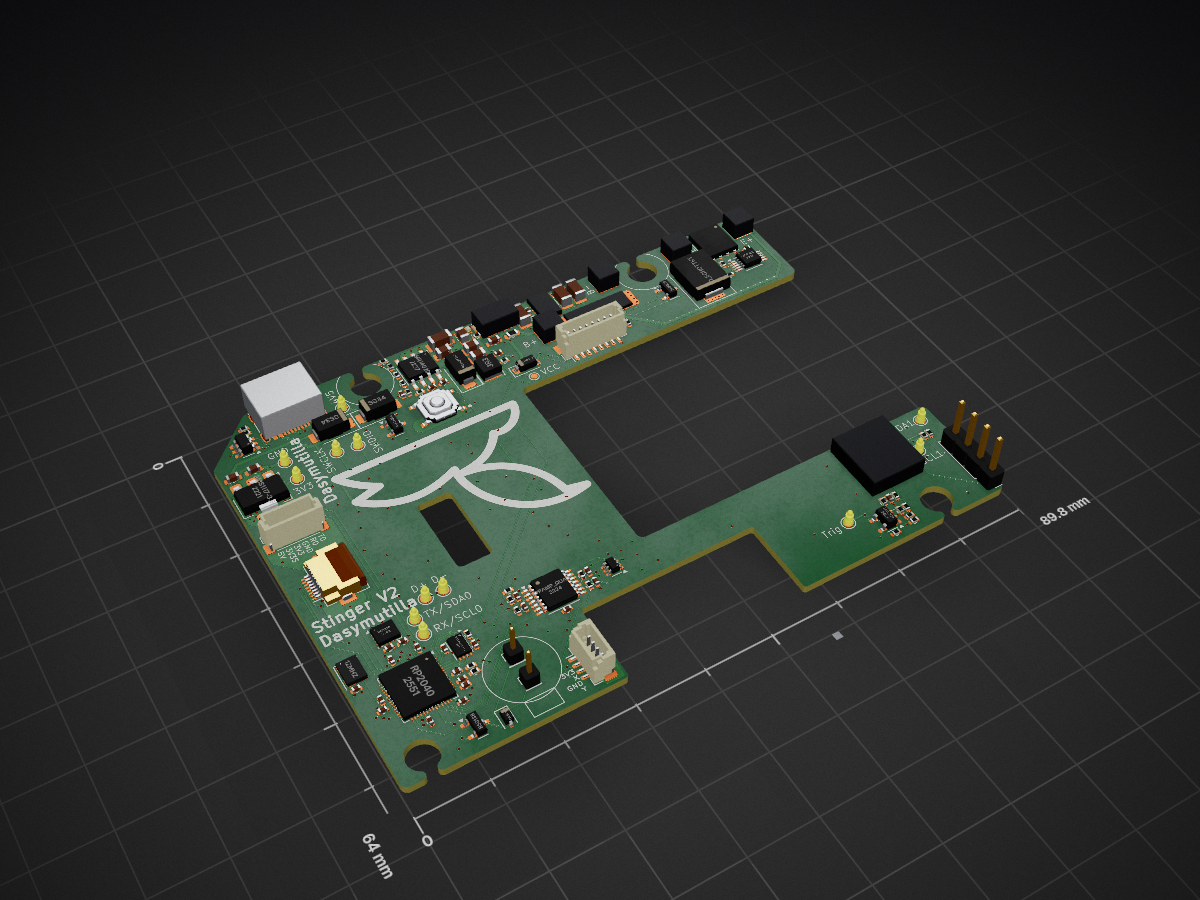
Stinger V2.0 is an open-source printed circuit board by Project-Stinger, from the Project-Stinger/Electronics repository on GitHub. It is a 4-layer board of 89.8 × 64 mm with 126 parts on 105 nets, routed with 1,008 tracks and 362 vias.
It is built around the RP2040, LM5060MM and LMV321, with the W25Q16JVUXIQ, 74LVC1G3157 and AMS1117-3.3 among its other parts. Its parts include 36 capacitors, 32 resistors, 14 connectors, 10 ICs and 10 diodes. It belongs with the RP2040 boards of this library.


This repository contains the electronics for the Stinger foam dart blaster. The main parts are:
Documentation for Stinger is provided in the Stinger-Docs wiki.
To make your own electronics, you will need to:
Because purchase links regularly change, you will need to search for the components yourself:
At last, please note that this work is licensed under the Creative Commons BY-NC-SA License. This means you can use the designs for non-commercial purposes, but you must give appropriate credit and share any derivative works under the same license. Also be aware that it is usually cheaper to buy the electronics because of many custom parts. The PCB is mainly provided for educational purposes and to allow you to make your own modifications or repairs.
This project is still in the early stages of making the source available. If you feel like something is missing in order to make this repo accessible, please open an issue or ask in the discussion forum.
| Qty | Value | Footprint | References |
|---|---|---|---|
| 18 | 100nF | Capacitor_SMD:C_0402_1005Metric | C1, C2, C3, C4, C5, C6, C7, C10, C13, C16, C17, C18, C19, C20, C24, C37 +2 |
| 12 | TestPoint_Probe | TestPoint:TestPoint_Pad_D1.5mm | TP1, TP2, TP4, TP5, TP6, TP7, TP8, TP9, TP10, TP11, TP12, TP13 |
| 9 | 10k | Resistor_SMD:R_0402_1005Metric | R6, R8, R9, R11, R12, R18, R20, R22, R29 |
| 5 | 100k | Resistor_SMD:R_0402_1005Metric | R5, R14, R16, R17, R31 |
| 4 | 1µF | Capacitor_SMD:C_0402_1005Metric | C11, C12, C14, C15 |
| 4 | 22µF | Capacitor_SMD:C_0805_2012Metric | C23, C26, C27, C28 |
| 4 | 5.1k | Resistor_SMD:R_0402_1005Metric | R3, R4, R10, R24 |
| 4 | ~ | components:big pad | P1, P2, P3, P4 |
| 3 | 10µF | Capacitor_SMD:C_1206_3216Metric | C38, C39, C40 |
| 2 | 10µF | Capacitor_SMD:C_0603_1608Metric | C33, C34 |
| 2 | 1k | Resistor_SMD:R_0402_1005Metric | R7, R15 |
| 2 | 27R | Resistor_SMD:R_0402_1005Metric | R1, R2 |
| 2 | 4.7k | Resistor_SMD:R_0402_1005Metric | R27, R28 |
| 2 | 510 | Resistor_SMD:R_0402_1005Metric | R21, R23 |
| 2 | Conn_01x01 | Connector_PinHeader_2.00mm:PinHeader_1x01_P2.00mm_Vertical | J4, J5 |
| 2 | LED | LED_SMD:LED_0402_1005Metric | D8, D9 |
| 2 | SS34 | Diode_SMD:D_SMA | D6, D7 |
| 2 | WS2812B-2020 | LED_SMD:LED_WS2812B-2020_PLCC4_2.0x2.0mm | D10, D11 |
| 2 | ~ | components:medium pad | P5, P6 |
| 1 | 1.25A | Fuse:Fuse_0603_1608Metric | F1 |
| 1 | 100K | Resistor_SMD:R_0402_1005Metric | R26 |
| 1 | 100nF | Capacitor_SMD:C_0603_1608Metric | C36 |
| 1 | 10nF | Capacitor_SMD:C_0402_1005Metric | C22 |
| 1 | 12MHz | Oscillator:Oscillator_SMD_Abracon_ASE-4Pin_3.2x2.5mm | X1 |
| 1 | 1M | Resistor_SMD:R_0402_1005Metric | R19 |
| 1 | 1N4148WS | Diode_SMD:D_SOD-323 | D4 |
| 1 | 220nF | Capacitor_SMD:C_0402_1005Metric | C35 |
| 1 | 2N7002 | Package_TO_SOT_SMD:SOT-23 | Q2 |
| 1 | 3.3µH | Inductor_SMD:L_Cenker_CKCS3015 | L1 |
| 1 | 31K | Resistor_SMD:R_0402_1005Metric | R32 |
| 1 | 330pF | Capacitor_SMD:C_0402_1005Metric | C25 |
| 1 | 4.7µF | Capacitor_SMD:C_1206_3216Metric | C21 |
| 1 | 40A | components:Fuse_10032Metric | F2 |
| 1 | 51k | Resistor_SMD:R_0402_1005Metric | R25 |
| 1 | 700 | Resistor_SMD:R_0402_1005Metric | R30 |
| 1 | 70k | Resistor_SMD:R_0402_1005Metric | R13 |
| 1 | 74LVC1G3157 | Package_TO_SOT_SMD:SOT-363_SC-70-6 | U13 |
| 1 | AMS1117-3.3 | Package_TO_SOT_SMD:SOT-223-3_TabPin2 | U11 |
| 1 | AO3401A | Package_TO_SOT_SMD:SOT-23 | Q3 |
| 1 | BMI270 | Package_LGA:Bosch_LGA-14_3x2.5mm_P0.5mm | U5 |
| 1 | BSC105N10LSFG | Package_TO_SOT_SMD:TDSON-8-1 | Q1 |
| 1 | BSS138 | Package_TO_SOT_SMD:SOT-23 | Q4 |
| 1 | Conn_01x04 | Connector_PinHeader_2.54mm:PinHeader_1x04_P2.54mm_Vertical | J6 |
| 1 | Conn_01x04_MountingPin | Connector_JST:JST_SH_BM04B-SRSS-TB_1x04-1MP_P1.00mm_Vertical | J7 |
| 1 | Conn_01x06_MountingPin | Connector_JST:JST_SH_BM06B-SRSS-TB_1x06-1MP_P1.00mm_Vertical | J8 |
| 1 | Conn_01x08_MountingPin | Connector_JST:JST_SH_BM08B-SRSS-TB_1x08-1MP_P1.00mm_Vertical | J2 |
| 1 | Conn_01x08_MountingPin | Connector_FFC-FPC:Hirose_FH12-8S-0.5SH_1x08-1MP_P0.50mm_Horizontal | J3 |
| 1 | D_Schottky | Diode_SMD:D_SMA | D1 |
| 1 | D_Schottky | Diode_SMD:D_SMC | D3 |
| 1 | D_Schottky | Diode_SMD:D_SOD-123 | D2 |
| 1 | LM5060 | Package_SO:VSSOP-10_3x3mm_P0.5mm | U16 |
| 1 | LMR14020 | Package_SO:HSOP-8-1EP_3.9x4.9mm_P1.27mm_EP2.41x3.1mm_ThermalVias | U7 |
| 1 | LMV321 | Package_TO_SOT_SMD:SOT-23-5 | U6 |
| 1 | Opamp_Quad | Package_SO:TSSOP-14_4.4x5mm_P0.65mm | U4 |
| 1 | RP2040 | Package_DFN_QFN:QFN-56-1EP_7x7mm_P0.4mm_EP3.2x3.2mm | U1 |
| 1 | TestPoint_Probe | TestPoint:TestPoint_Pad_D1.0mm | TP3 |
| 1 | USB_C_Receptacle_USB2.0_16P | components:USB-C | J1 |
| 1 | W25Q16JVUXIQ | Package_SON:Winbond_USON-8-1EP_3x2mm_P0.5mm_EP0.2x1.6mm | U2 |
| 1 | WE-TVS-824015043 | Package_TO_SOT_SMD:SOT-23-6 | U3 |
| 1 | ~ | components:button trigger | BN2 |
| 1 | ~ | components:QFN14-3x4.5_sharedPads | DR1 |
| 1 | ~ | components:button | BN1 |
It measures 89.8 × 64 mm and has 4 copper layers, 1.2 mm thick.
126 parts, built around the RP2040, LM5060MM, LMV321 and W25Q16JVUXIQ. The full list of its parts is on this page, with links to each part's symbol and footprint where PCBKit's library has them.
From the Project-Stinger/Electronics repository on GitHub, at the commit this page was made from: the board is V2 PCB/Stinger V2.0.kicad_pcb and its schematic V2 PCB/Stinger V2.0.kicad_sch. PCBKit opens the board in the browser, with nothing to install.
Its repository states no licence, so its author keeps all rights: ask Project-Stinger before reusing the design.

rjsc/BECom
BECom - Battery Emulator Companion - Open Source Hardware, designed to run dalathegreat/Battery-Emulator

motionlayer/Dianome
Docs, Schematic and Board file for the Dianome PDB


EdgeCoil/wiegand-bridge
ESP32-S3 Wiegand reader bridge for Home Assistant: 4-layer board, BOM and ESPHome firmware.

nordstream3/FOC
Date | Manufacturer | amount | includes | shipping & tax | price | -------- | -------- | -------- | -------- | -------- | -------- | 2024-01-17 | JLCPCB | 10 boards | All assembled excl fets and caps | YES, to EU |…